Genicom MatrixPrinter LA36 User Manual
Page 118
5-31
5.3.5
Print head control
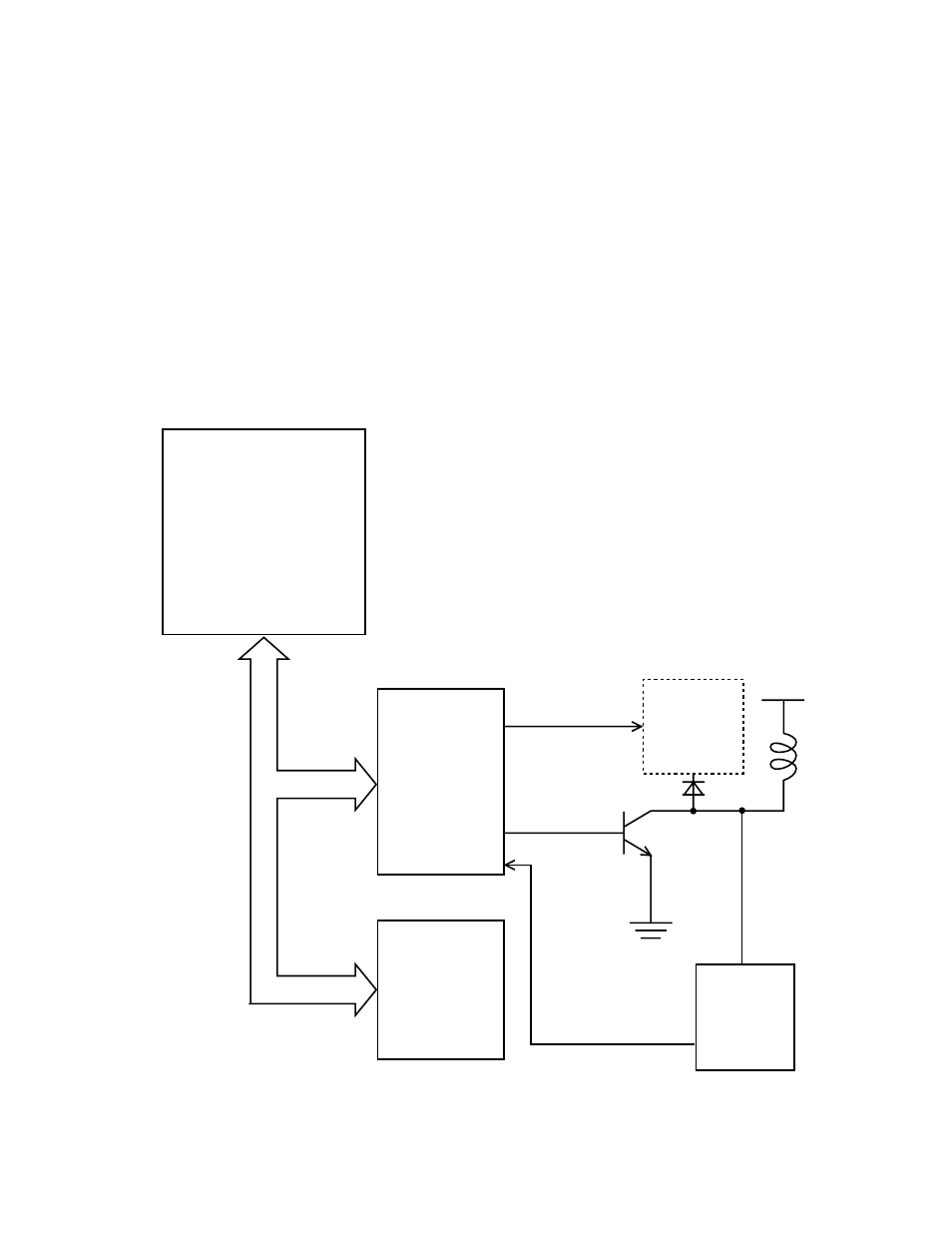
Operation from reading print data to driving the pin magnet is as follows (Figure 5.30):
1.
Print data is read from line buffer RAM.
2.
Data is sent to the HDLSI(MBCU20050), being set to high for dots to be printed.
3.
Excitation and flyback absorption timers are in the HDLSI.
4.
Print data and excitation time are ANDed and, the result is output by the HDLSI, then the print head drive
transistor is turned on.
Figure 5.30 Print head pin magnet drive circuit
MPU
MB90706
HDLSI
MBCU20050
RAM
FLYBK1
~FLYBK6
PD01~PD24
Flyback
absorbing
circuit
+34V
Fire
Check
Circuit
HALM1
~HALM4
HDALM1
~HDALM4