FUJITSU C145-C037-01EN User Manual
Page 63
5-15
5.4.3
Serial data format
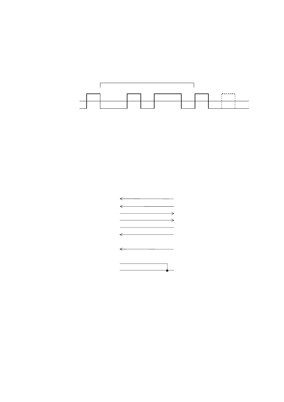
The format of 10-bit or 11-bit serial data, given in Figure 5.12, consists of a start bit, data bits, a parity bit, and stop
bits. A bit is in the mark state when not being transmitted. Data bits start with the least significant bit (LSB). For
example, the character “K” (hexadecimal 4B) is transmitted as shown in Figure 5.12 (7 data bits, even parity).
Start
bit
Parity
bit
Stop
bit(s)
Data bits
High, +, or Space
Low, –, or Mark
0
0
0
0
0
1
1
1
1
3
5
6
1
2
4
7
1
(1)
Figure 5.12 RS-232C data format
5.4.4
Cable connection diagrams
The connector at the printer side is a 9-pin type. The connector at the computer side is a 9-pin type or a 25-pin type.
CD
RD
TD
DTR
SG
DSR
RTS
CTS
RI
FG
RTS
TD
RD
DSR
SG
DTR
#
DTR
#
Shell
(pin 8)
(pin 3)
(pin 2)
(pin 20)
(pin 7)
(pin 6)
(pin 4)
(pin 5)
(pin 22)
(pin 1)
Shell
Computer (DTE)
Printer (DTE)
# Open wire
(pin 1)
(pin 2)
(pin 3)
(pin 4)
(pin 5)
(pin 6)
(pin 7)
(pin 8)
(pin 9)
Figure 5.13a Example of RS-232C cable wiring (25-pin connector at computer side)
- FTP-633GA1021 (6 pages)
- KA02038-Y820 (1 page)
- FTP-632MCL102 (7 pages)
- FTP-621MCL102 (6 pages)
- FTP-604 FTP-644MCL002 (7 pages)
- FTP-629MCL103-R (7 pages)
- FTP-641MCL351 (6 pages)
- FTP-030P (3 pages)
- FTP-627USL401 (9 pages)
- FTP-621CT001 (6 pages)
- FTP-629MCL054 (7 pages)
- FTP-634MCL001 (7 pages)
- FTP-624MCL002 (8 pages)
- Printer (4 pages)
- FTP-040HF Holder Series (2 pages)
- P3PC-1442-01EN (17 pages)
- FTP-631MCL201 (6 pages)
- FTP-628WSL120 (7 pages)
- ScandAll PRO P2WW-2410-01ENZ0 (45 pages)
- DL6400Pro (247 pages)
- FTP-632MCL003 (7 pages)
- FTP-633MCL400 (12 pages)
- FTP-631MCL302 (6 pages)
- 102 (8 pages)
- FTP-622MCL302 (6 pages)
- FTP-642MCL302 (7 pages)
- 16DV (39 pages)
- FTP-639MCL103/383-R (7 pages)
- FTP-637MCL401 (6 pages)
- DL9400 (250 pages)
- M304X (143 pages)
- FTP-631MCL352 (6 pages)
- FTP-631MCL101 (6 pages)
- FTP-639MCL353 (7 pages)
- FTP-641MCL302 (6 pages)
- FTP-622DCL001/011 (8 pages)
- FTP-628MCL401 (9 pages)
- FTP-621MCL201 (6 pages)
- FTP-641MCL101/102 (6 pages)
- FTP-632MCL301 (6 pages)
- DL3800 (262 pages)
- DL6400 (247 pages)
- FTP-627USL631 (10 pages)
- FTP-624MCL304 (7 pages)