FUJITSU C145-C037-01EN User Manual
Page 58
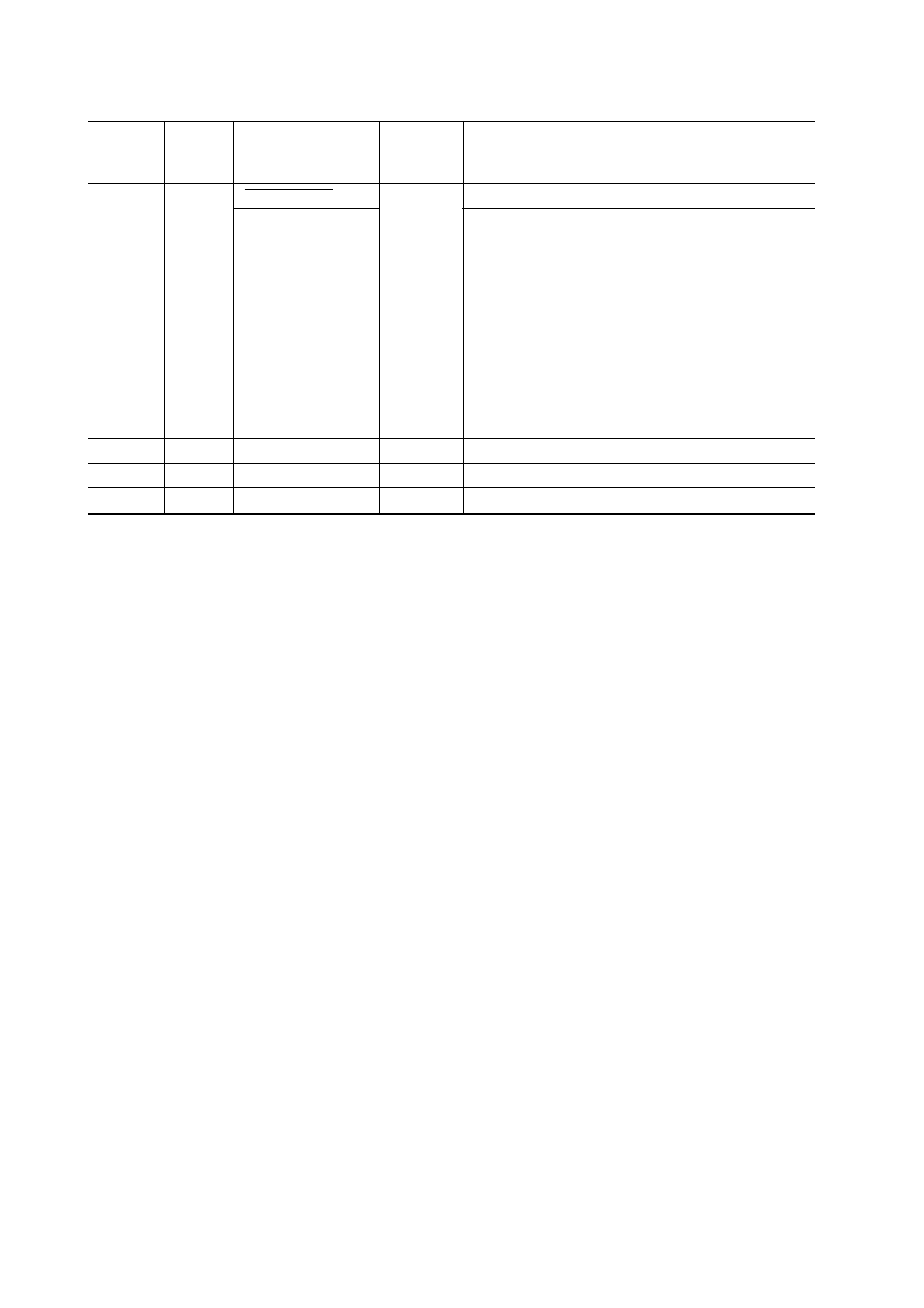
5-10
Connector
pin
number
17
18
19 to 35
36
Return
line pin
number
35
–
–
–
Direction
Input
Input
–
Output
Description
Reserved (*1)
Reverse data transfer phase:
This signal is set low when the host can receive data,
and goes high when the host has received data.
Following a reverse data transfer, the interface enters
the reverse idle phase when the Host Busy signal goes
low and the printer has no data.
Reverse idle phase:
This signal goes high when the Printer Clock signal
goes low so that the interface re-enters the reverse
data transfer phase. If it goes high with the 1284
Active signal low, the 1284 idle phase is aborted and
the interface returns to the compatibility mode.
Host Logic High
Twisted-pair return lines
Peripheral Logic High
Signal
Compati mode
Nibble mode
Auto Feed XT
Host Busy
–
Signal Ground (SG)
–
Table 5.2 Parallel interface signals (continued)
*1 Assigned as a signal name, without any function.
Notes:
1.
Left-aligned signal names are in compati mode and right-aligned ones are in nibble mode.
2.
The direction (input and output) refers to the printer.
3.
Return line: Twisted-pair return line connected to the signal ground level