FUJITSU C145-C037-01EN User Manual
Page 62
5-14
5.4.2
Connector pin assignment
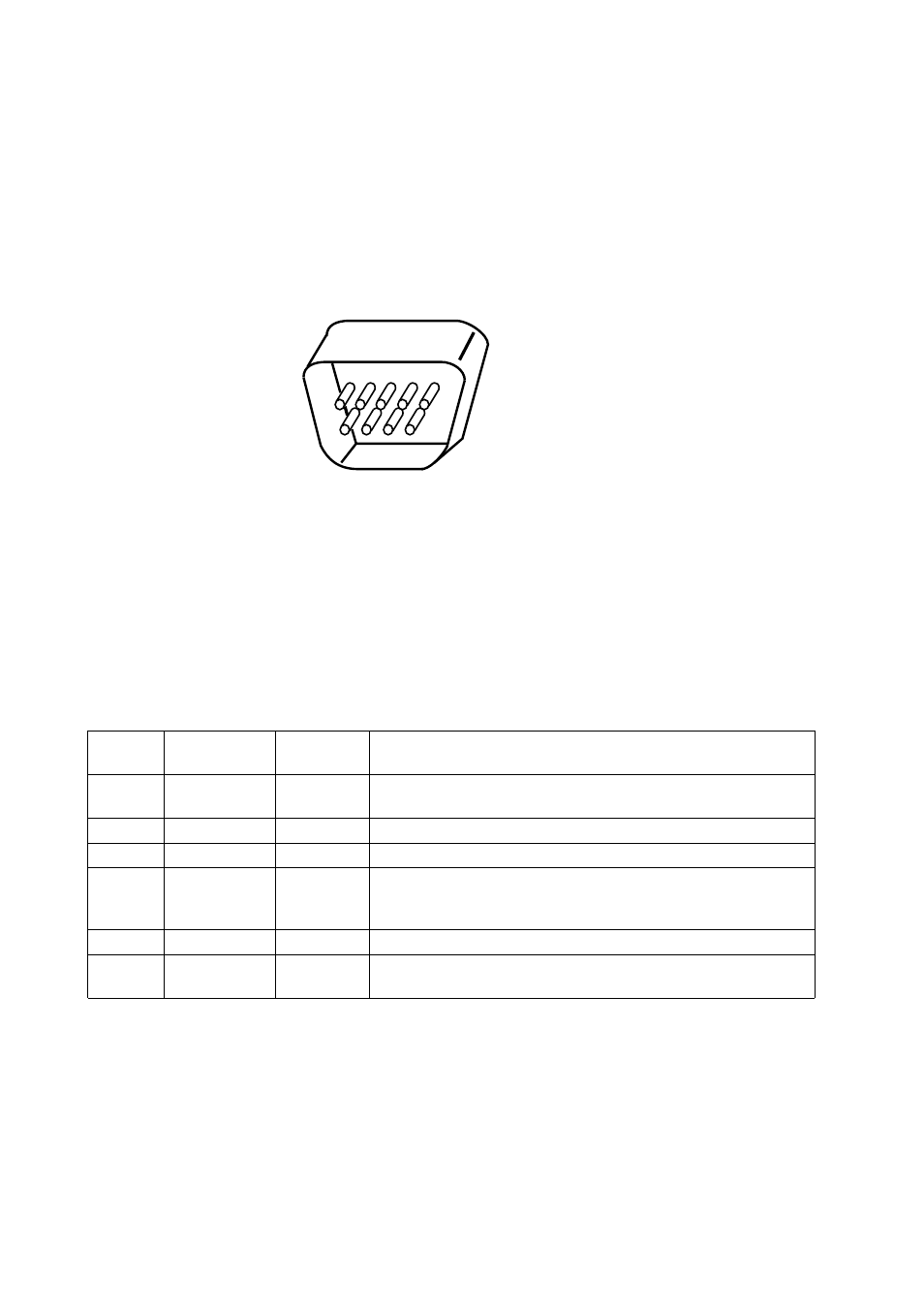
Connector (cable side):
D-subminiature Cannon or Cinch DB-9 plug or an equivalent connector that conforms to EIA standards
Figure 5.11 shows the serial interface connector.
Figure 5.11 Serial interface connector
Signal definition:
Table 5.3 lists RS-232C interface signals and their functions.
(Cable side)
(Male type)
1
6
5
9
Table 5.3 RS-232C interface signals
Pin
number
1
2
3
4
5
6, 8
Description
Request to Send
Space state when the printer is ready to transmit data
Transmitting Data
Receiving Data
Data Set Ready
The printer can receive or transmit data when this signal is in the
space state.
Signal Ground (common return)
Data Terminal Ready
Space state when the printer is ready to receive or transmit data
Signal name
RTS
TD
RD
DSR
SG
DTR
Direction
Output
Output
Input
Input
Output
Notes:
1.
The space state corresponds to the high level of the interface signal.
2.
The direction (output or input) is viewed from the printer side.
- FTP-633GA1021 (6 pages)
- KA02038-Y820 (1 page)
- FTP-632MCL102 (7 pages)
- FTP-621MCL102 (6 pages)
- FTP-604 FTP-644MCL002 (7 pages)
- FTP-629MCL103-R (7 pages)
- FTP-641MCL351 (6 pages)
- FTP-030P (3 pages)
- FTP-627USL401 (9 pages)
- FTP-621CT001 (6 pages)
- FTP-629MCL054 (7 pages)
- FTP-634MCL001 (7 pages)
- FTP-624MCL002 (8 pages)
- Printer (4 pages)
- FTP-040HF Holder Series (2 pages)
- P3PC-1442-01EN (17 pages)
- FTP-631MCL201 (6 pages)
- FTP-628WSL120 (7 pages)
- ScandAll PRO P2WW-2410-01ENZ0 (45 pages)
- DL6400Pro (247 pages)
- FTP-632MCL003 (7 pages)
- FTP-633MCL400 (12 pages)
- FTP-631MCL302 (6 pages)
- 102 (8 pages)
- FTP-622MCL302 (6 pages)
- FTP-642MCL302 (7 pages)
- 16DV (39 pages)
- FTP-639MCL103/383-R (7 pages)
- FTP-637MCL401 (6 pages)
- DL9400 (250 pages)
- M304X (143 pages)
- FTP-631MCL352 (6 pages)
- FTP-631MCL101 (6 pages)
- FTP-639MCL353 (7 pages)
- FTP-641MCL302 (6 pages)
- FTP-622DCL001/011 (8 pages)
- FTP-628MCL401 (9 pages)
- FTP-621MCL201 (6 pages)
- FTP-641MCL101/102 (6 pages)
- FTP-632MCL301 (6 pages)
- DL3800 (262 pages)
- DL6400 (247 pages)
- FTP-627USL631 (10 pages)
- FTP-624MCL304 (7 pages)