FUJITSU C145-C037-01EN User Manual
Page 56
5-8
5.3.2
Connector pin assignment
Connector (cable side): Shielded plug
MOLEX 52316-3611 (shielded cover kit with latches) or equivalent
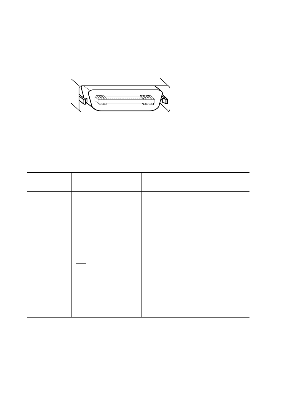
Figure 5.7 shows the parallel interface connector.
Figure 5.7 Parallel interface connector (IEEE1284-C)
Signal definition:
Table 5.2 lists parallel interface signals and their functions.
Table 5.2 Parallel interface signals
(Cable side)
(Male type)
36
18
1
19
Return
line pin
number
19
20
21
Signal
Compati mode
Nibble mode
Busy
Printer Busy
Select (SLCT)
X Flag
Acknowledge
(ACK)
Printer Clock
Description
Data cannot be received when this signal is high,
e.g., if the buffer is full or an error occurs.
Reverse data transfer phase:
Data bit 3, data bit 7, then forward path (host to
printer) busy status
This signal goes high when the printer is selected
(online), and goes low when the printer is deselected
(offline).
Reverse data transfer phase:
Data bit 1, then data bit 5
• Pulse signal indicating data reception completed
(or data reception enabled) status
• Issued when the printer switches from offline to
online
Reverse data transfer phase:
This signal goes high when data being sent to the
host is established.
Reverse idle phase:
This signal is set low then goes high to interrupt the
host, indicating that data is available.
Connector
pin
number
1
2
3
Direction
Output
Output
Output