FUJITSU MCE3130AP User Manual
Page 61
C156-E142-02EN
3 - 15
(2)
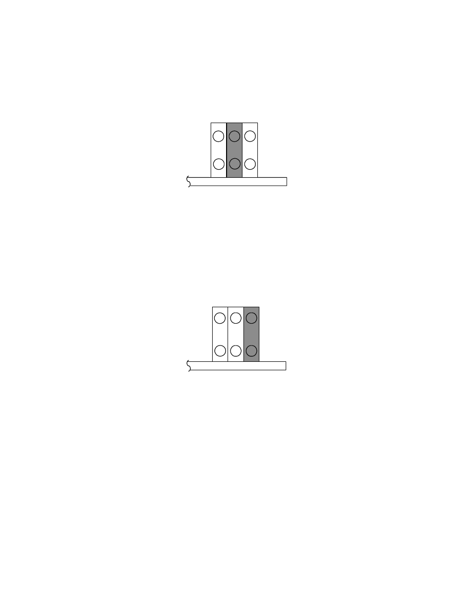
Setting slave device mode
Figure 3.13 shows the setting for recognizing the slave device (device 1).
CNH1
3
1
4
2
5
6
Figure 3.13 Slave device setting
(3)
Setting cable select mode
Figure 1.14 shows the master device/slave device setting when the CSEL signal is connected to the
interface. In the example shown in Figure 3.16, this setting requires a special interface connection.
CNH5
3
1
4
2
5
6
Figure 3.14 Cable select mode setting
Figure 3.15 shows a cable select example using a special interface cable.
This example connects CSEL of the master device to the CSEL line (conductor) of the cable, then
grounds it so that the drive recognizes that it is the master. At this time, the CSEL conductor of the
slave device is removed and cannot be connected to CSEL of the cable, so that the drive
recognizes that it is the slave.
CNH5