4 notes on mounting – FUJITSU MCE3130AP User Manual
Page 55
C156-E142-02EN
3 - 9
3.2.4
Notes on mounting
(1)
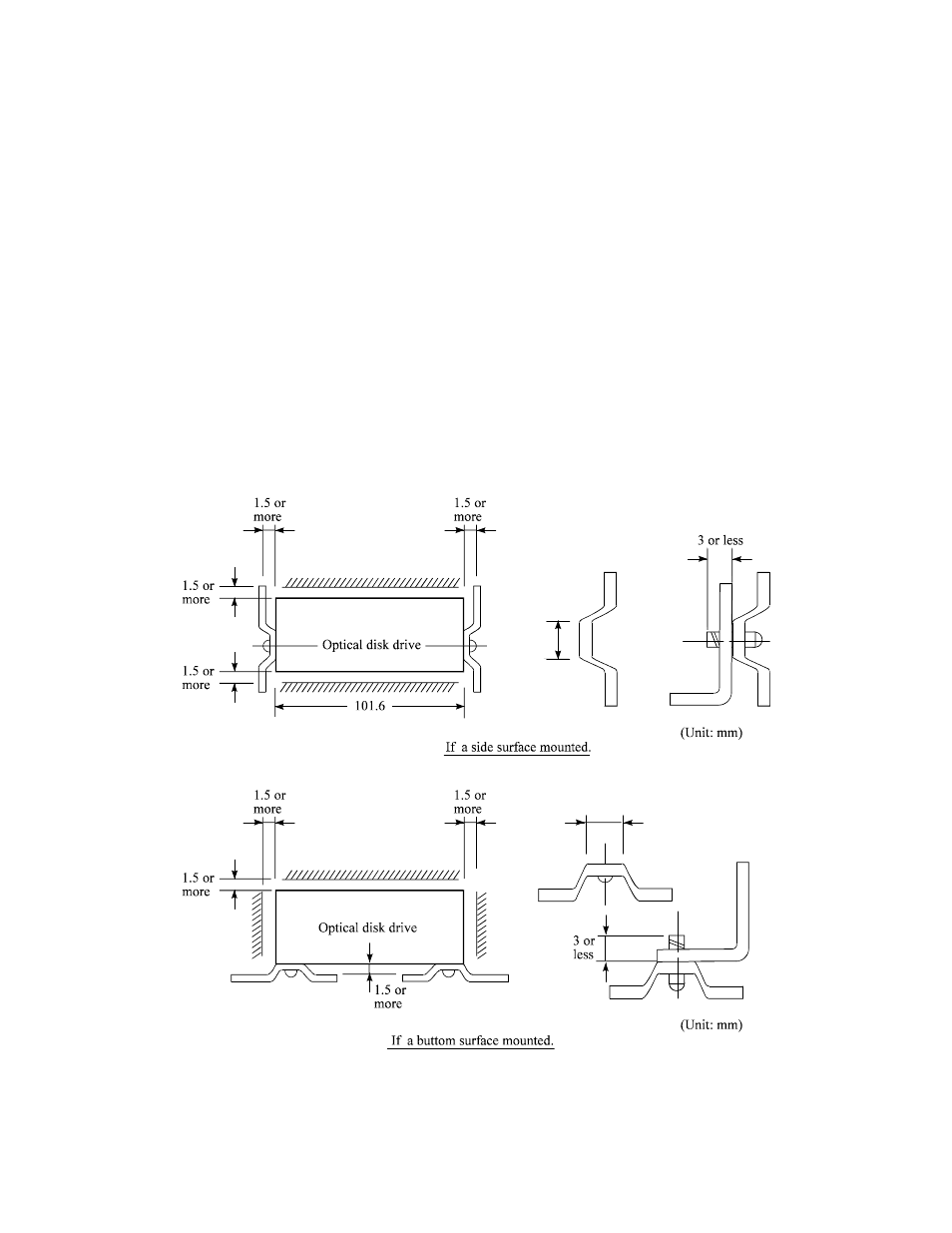
Mounting frame structure and clearance
a) For vibration resistance and heat dissipation, this optical disk drive uses an embossed structure
as shown in Figure 3.6, as well as a frame which has a construction similar to other frames
which perform the same function.
b) As shown in Figure 3.6, the inward projection of the mounting screw from the outer surface of
the drive frame must not exceed 3 mm.
c) The clearance between the external surface of the drive frame and the user's frame structure
must be at least 1.5 mm.
d) The clearance between the top and bottom surfaces and the user's frame structure must be at
least 1.5 mm.
e) When mounting the optical disk drive, the screw tightening torque should be 0.4 to 0.45Nm (4
to 4.6kgcm).
f) When the optical disk drive (with panel) is mounted in a locker, there should be no
deformation of the mounting fittings provided and the optical disk drive's panel should not be
deformed. If the drive is used with the panel deformed, ejection of the cartridge will be faulty.
Check if the door will close from any position whatever when the optical disk drive is installed.
Figure 3.6
Mounting frame structure
$15
or less
$15
or less