Figure 2-7. moment of inertia calculation examples – Adept s1300 Viper User Manual
Page 31
Designing End-Effectors
Adept Viper s1300 Robot User’s Guide, Rev B
31
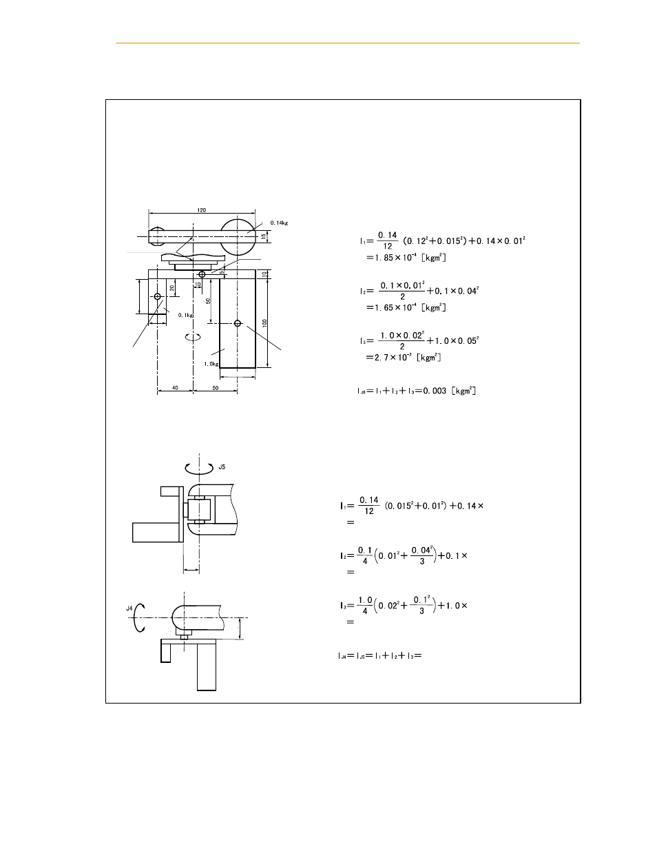
Figure 2-7. Moment of Inertia Calculation Examples
Calculation example : When calculating the
moment of inertia of a complicated shape, divide it into
simple parts as much as possible for easier calculations.
As shown in the figure below, divide the end-effector into three parts (
Q, R, S).
(1) Moment of inertia around J6
Unit: mm
Robot flange
center
Q
R
S
φ20
φ40
φ40
Moment of inertia around J6 of
Q: I
1
(from 3 and 5 in Table 2-3)
Moment of inertia around J6 of
R: I
2
(from 1 and 5 in Table 2-3)
Moment of inertia around J6 of
S: I
3
(from 1 and 5 in Table 2-3)
Moment of inertia around J6 of entire end-effector: I
J6
(2) Moment of inertia around J4 and J5
For the end-effector shown below, the moment of
inertia around J4 and J5 can be calculated according
to the same formula.
80
80
((0.08 + 0.005)
2
+0.01)
1.03
× 10
-3
[kgm
2
]
1.39
× 10
-3
[kgm
2
]
2.30
× 10
-3
[kgm
2
]
2.54
×10
-2
[kgm
2
]
((0.08 + 0.01 + 0.02)
2
+0.04
2
)
((0.08 + 0.01 + 0.05)
2
+0.05
2
)
Moment of inertia around J4 and J5 of
Q: I
1
(from 3 and 5 in Table 2-3)
Moment of inertia around J4 and J5 of
R: I
2
(from 2 and 5 in Table 2-3)
Moment of inertia around J4 and J5 of
S: I
3
(from 2 and 5 in Table 2-3)
Moment of inertia around J4 and J5 of entire end-effector: I
J4
, I
J5
Center of
gravity of
Q
Center of
gravity of
S
Center of
gravity of
R
Around J6
Around J6
Table 3-5
Table 3-5
Table 3-5
Table 3-5
Table 3-5
Table 3-5