Moment of inertia around j4, j5 and j6 – Adept s1300 Viper User Manual
Page 30
Chapter 2 - Robot Installation
30
Adept Viper s1300 Robot User’s Guide, Rev B
Moment of Inertia Around J4, J5 and J6
Design an end-effector so that its moments of inertia around J4, J5, and J6 (including
workpiece) do not exceed the maximum allowable moment of inertia of the robot.
Moment of inertia around J4, J5, and J6 of end-effector (including mass of workpiece)
must be less than or equal to the maximum allowable moment of inertia
Maximum allowable moment of inertia around J4 and J5: 0.36 kgm
2
Maximum allowable moment of inertia around J6: 0.064 kgm
2
When calculating the moment of inertia around J4, J5, and J6 of the end-effector, use the
formulas given in
, and see examples in
.
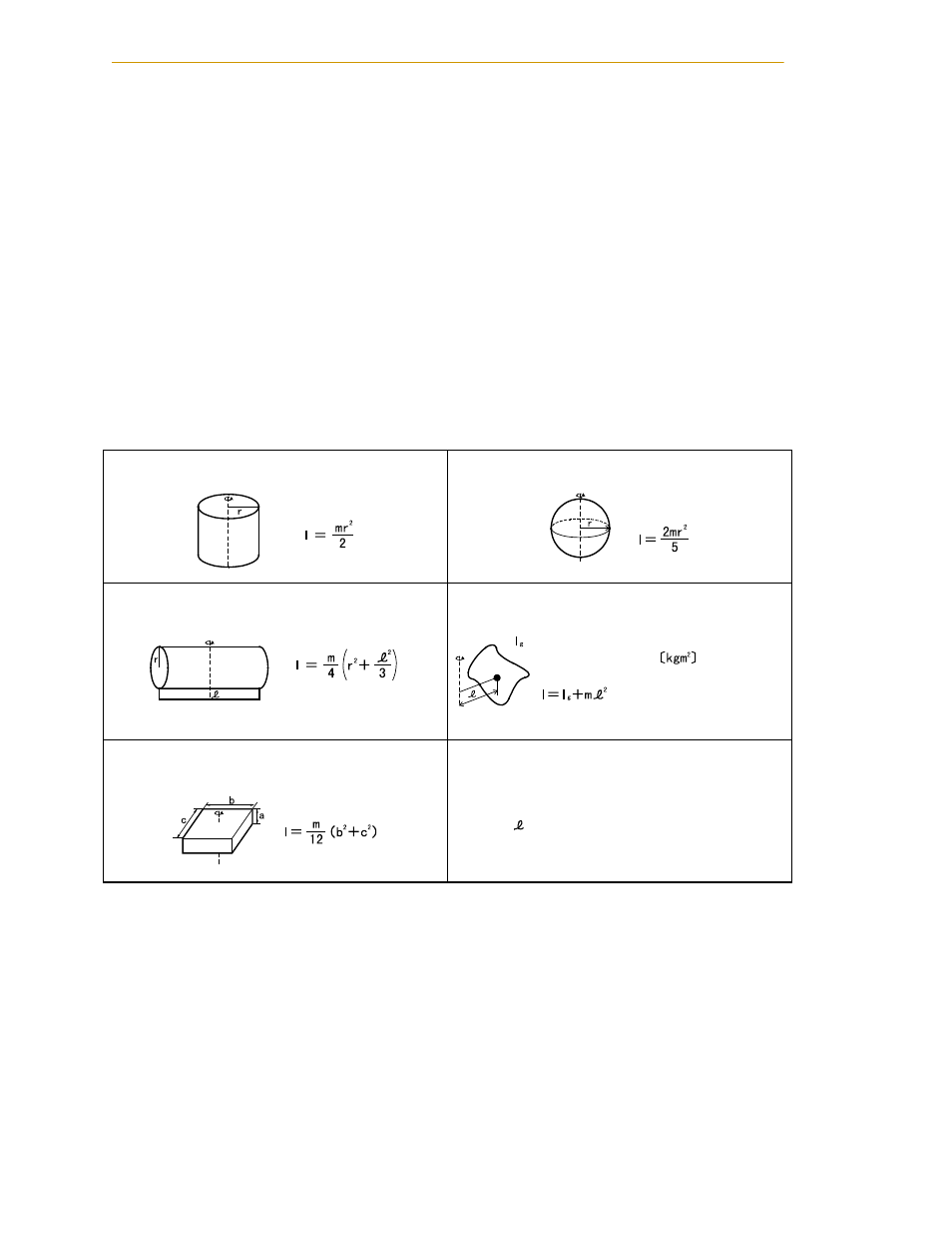
Table 2-5. Moment of Inertia Formulas
1. Cylinder (1)
(Axis of rotation = Center axis)
4. Sphere
(Axis of rotation = Center axis)
2. Cylinder (2)
(The axis of rotation passes through the center of gravity.)
5. Center of gravity not on the axis of rotation
:
3. Rectangular parallelepiped
(The axis of rotation passes through the center of gravity.)
l:
Moment of inertia
❲kgm
2
❳
m:
Mass
❲kg❳
r:
Radius
❲m❳
b, c, :
Length
❲m❳
Inertia moment around center of gravity