7 air lines and signal wiring, L. see, Section 2.7 on – Adept s1300 Viper User Manual
Page 25: B) (a)
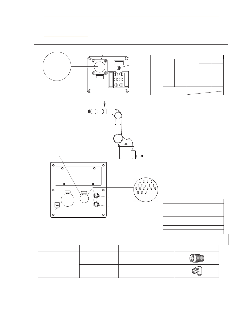
Air Lines and Signal Wiring
Adept Viper s1300 Robot User’s Guide, Rev B
25
2.7
Air Lines and Signal Wiring
CN20 pin No.
Used for:
12
0V
13
Solenoid 1A (solenoid valve 1)
14
Solenoid 1B (solenoid valve 1)
15
Solenoid 2A (solenoid valve 2)
16
Solenoid 2B (solenoid valve 2)
17
Solenoid 3A (solenoid valve 3)
18
Solenoid 3B (solenoid valve 3)
Note 1: Pin #1 to #10 on CN21 and those on CN20 are connected with each other. The allowable current per line is 1 A.
Note 2: Use the supplied connector sets for CN20 and CN21.
e
c
n
a
r
a
e
p
p
A
e
m
a
n
t
r
a
p
d
n
a
l
e
d
o
M
.
o
N
t
r
a
p
t
e
s
r
o
t
c
e
n
n
o
C
for CN20
for CN21
SRCN6A25-24S
(round type connector)
(Japan Aviation Electronics Industry Ltd)
05019-000
JMLP1610M
(L type plug connector)
DDK Electronics, Inc.
Air Piping
Joint (M5)
Valve Symbols and Air Intake and Exhaust States
(1A and 1B are piping joint symbols.)
Air piping joint
Valve signal
Solenoid
Air
intake
Exhaust
Solenoid
valve
A
B
1A
1B
1
ON
OFF
1B
1A
1
OFF
ON
2A
2B
2
ON
OFF
2B
2A
2
OFF
ON
3A
3B
3
ON
OFF
AIR1
3B
3A
3
OFF
ON
AIR2
Connector (CN20) for end-effector
signal/valve control wires
View (B)
AIR1 piping joint
(BSPT 1/4)
AIR2 piping joint
(BSPT 1/4)
CN20 pin layout
CN21 pin layout
View (A)
CN21 for end-effector
control signal wires
(B)
(A)
For controller I/O unit, PNP type
(sink IN, source OUT)
A I R 1
C N 2 0
C N 2 2
A I R 2
1A
2A
3A
1B
2B
3B
AIR2
CN21
● ● ●
● ● ●
● ● ● ●
3 2 1
7 6 5 4
10 9 8