2 demonstration projects – Impulse MAQ20-940 User Manual User Manual
Page 60
ReDAQ
®
Shape Software for MAQ
®
20 User Manual
60
6.2 Demonstration Projects
The ReDAQ Shape Software for MAQ
®
20 download comes with 9 demonstration projects which show
how to use the many available Tools. These projects are located in the ReDAQ Shape Software for
MAQ
®
20 base file folders for both the Developer and User versions which have default locations and
names of …\Dataforth\MAQ20\ReDAQ Shape MAQ20 Vx.xx Developer and …\Dataforth\MAQ20\ReDAQ
Shape MAQ20 Vx.xx User respectively. Project filenames are
and
Shape Software for MAQ
®
20, then select and open the project from the directory above. Next, set the
Acquire -> Communications tab parameters to match the settings on the MAQ
®
20 and on the host
computer. This includes System, Slave ID, choice of TCP/IP or Serial communications, IP address, Port
Name, Baud Rate and Parity. Press the Start icon and the project will run. All projects are interactive so
the user can adjust inputs on the MAQ
®
20 and force change on the project display as well as provide
input from the project panel and force change on the MAQ
®
20 hardware.
The Demonstration Projects are summarized below:
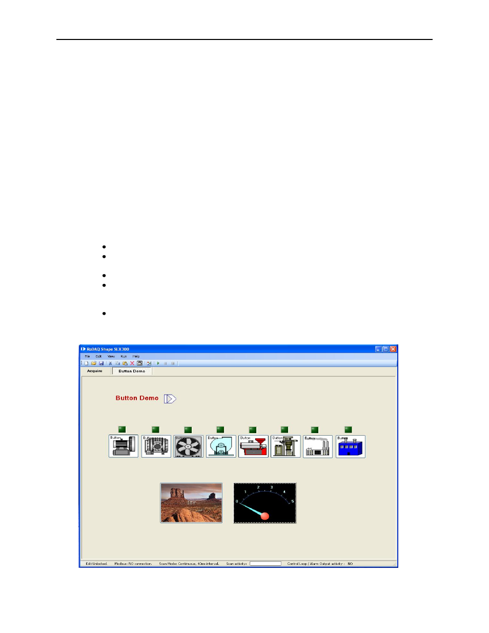
6.2.1 Demonstration Project #1: Button and Meter Tool Interface to I/O Channels
Filename Demo_Button.rsd or Demo_Button.rsu
8 Button Tools are connected to discrete output channels. Clicking on the buttons in the
project will turn the discrete output channels on and off.
An LED Tool above each button on the project shows the state of each output.
The Button Tool with the graphic image connects to analog output channel. The preset
output value is 2.5V. When the button is pressed, the default output value is sent to the
output channel. The preset value will be output to the field side terminal blocks.
A Meter Tool is assigned to an analog input channel. Wire the output of analog output
channel to the input of analog input channel. The Meter will now show the value of the
output channel.