9 power switch assembly, 9 power switch assembly –15 – HP DX2000 User Manual
Page 57
Service Reference Guide, dx2000 uT
359782-002
6–15
Removal and Replacement Procedures— Microtower (µT) Chassis
6.9 Power Switch Assembly
1. Prepare the computer for disassembly (
Section 6.1, “Preparation for Disassembly”
).
2. Remove the right access panel (
3. Remove the front bezel (
.
4. Remove the diskette drive (
Section 6.7.3, “Removing a Diskette Drive”
5. Disconnect the power, and data cables from the back of all installed 3.5" drives.
6. Remove the lower drive cage (
Section 6.7.4, “Removing the Lower Drive Cage”
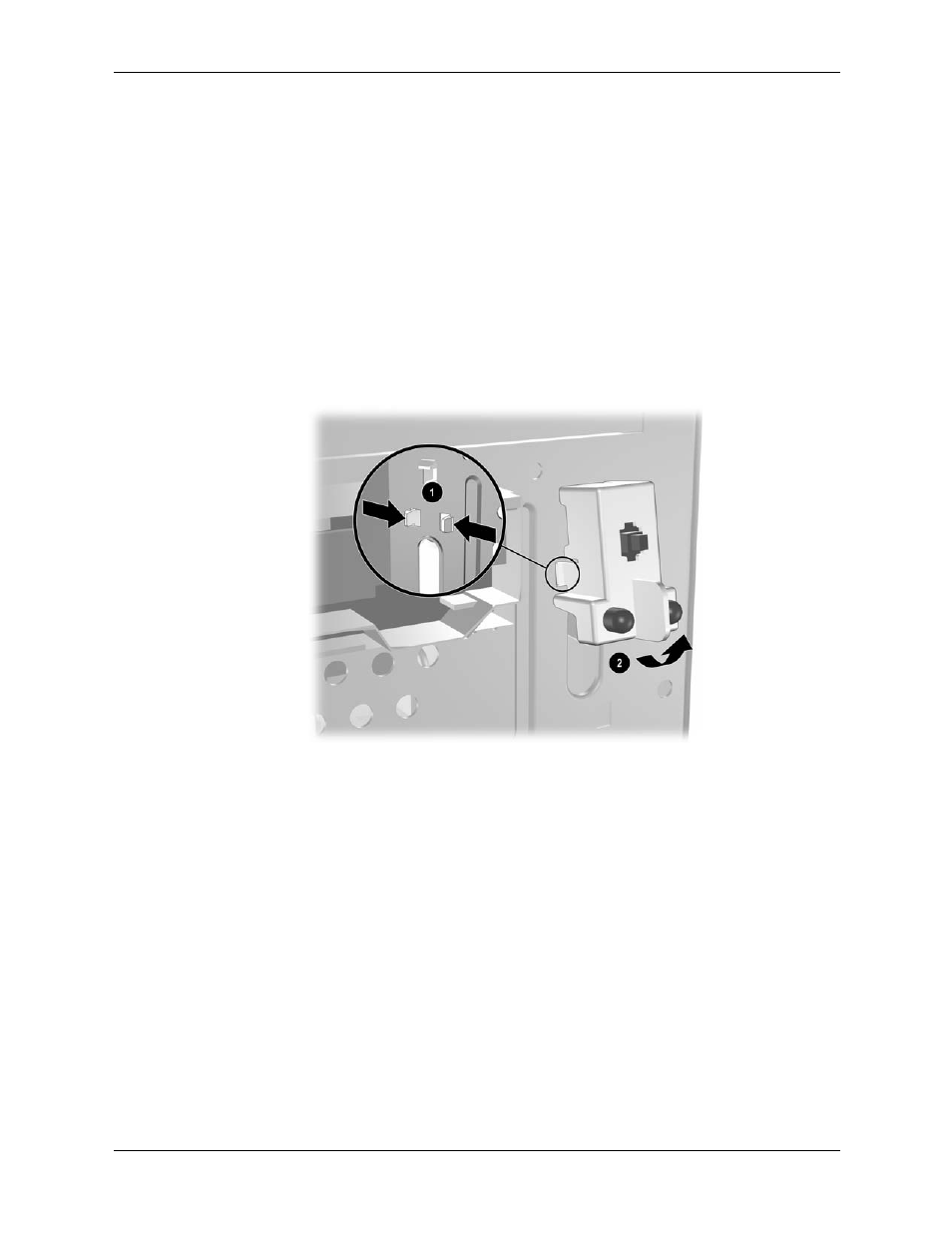
7. Disconnect the power switch cable from the system board.
8. From the inside of the chassis, squeeze the two lower retaining clips together 1 while
rotating the bottom of the power switch out of the chassis 2.
To install the power switch assembly, reverse the removal procedure.
- UX B6941-90001 (548 pages)
- A3661B (95 pages)
- C100/110 (252 pages)
- L1702 (45 pages)
- 576X-B (1 page)
- rx5670 (13 pages)
- ProLiant PC2-6400 (38 pages)
- PC (120 pages)
- S3240 (2 pages)
- LC 2000R (194 pages)
- GS80 (41 pages)
- COMPAQ DX2710 MT (107 pages)
- TOUCHSMART 9100 (62 pages)
- BC1500 (13 pages)
- Proliant DL580 (53 pages)
- Proliant DL580 (48 pages)
- DX2200 (31 pages)
- ProLiant Server Blade BL460c (31 pages)
- P6000 (105 pages)
- d530 Series (2 pages)
- dc5700 (216 pages)
- RX7620-16 (43 pages)
- ProLiant ML370 G5 (46 pages)
- PROLIANT ML350 G6 (54 pages)
- BL35P (22 pages)
- COMPAQ DC5750 (214 pages)
- Agent-Desktop-Laptop Computer (23 pages)
- DL380 G7 (126 pages)
- xw8600 (73 pages)
- Pavilion A6140 (2 pages)
- Z800 (55 pages)
- 8080 ELITE BUSINESS (284 pages)
- Vectra XE320 (82 pages)
- Vectra XE320 (32 pages)
- VECTRA VL800 (72 pages)
- AA-RTDRB-TE (146 pages)
- BL465C (66 pages)
- DM4 (113 pages)
- PROLIANT 580554-001 (87 pages)
- ProLiant ML330 (34 pages)
- ProLiant ML330 (44 pages)
- PROLIANT BL465C G7 (30 pages)
- LH 3r (23 pages)
- Compaq dc7900 (3 pages)
- T5000 (41 pages)