HP 480-0005-00-15 User Manual
Page 48
P/N 480-0005-00-15
2-24
Chapter 2: Hardware Components
Span Status LEDs. The DS1 card contains eight Span Status LEDs, viewable from the front of the chassis, to
provide a high level indication of the traffic status between the T1/E1 lines (also available on the rear of the
chassis) and the network equipment (i.e., PBX or PSTN). Each LED relates to one line on the rear of the DS1
card.
•
Off. SPAN is not connected. See Chapter 8: Diagnostics/Maintenance for a detailed description and
troubleshooting techniques.
•
Green. Line is operating properly.
•
Red. Local alarm generated (i.e., loss of framing).
•
Amber. Remote alarm generated (i.e., remote side has a problem and is sending a Yellow alarm).
Hot Swap LED. A lit blue light indicates that the DS1 card is not in service.
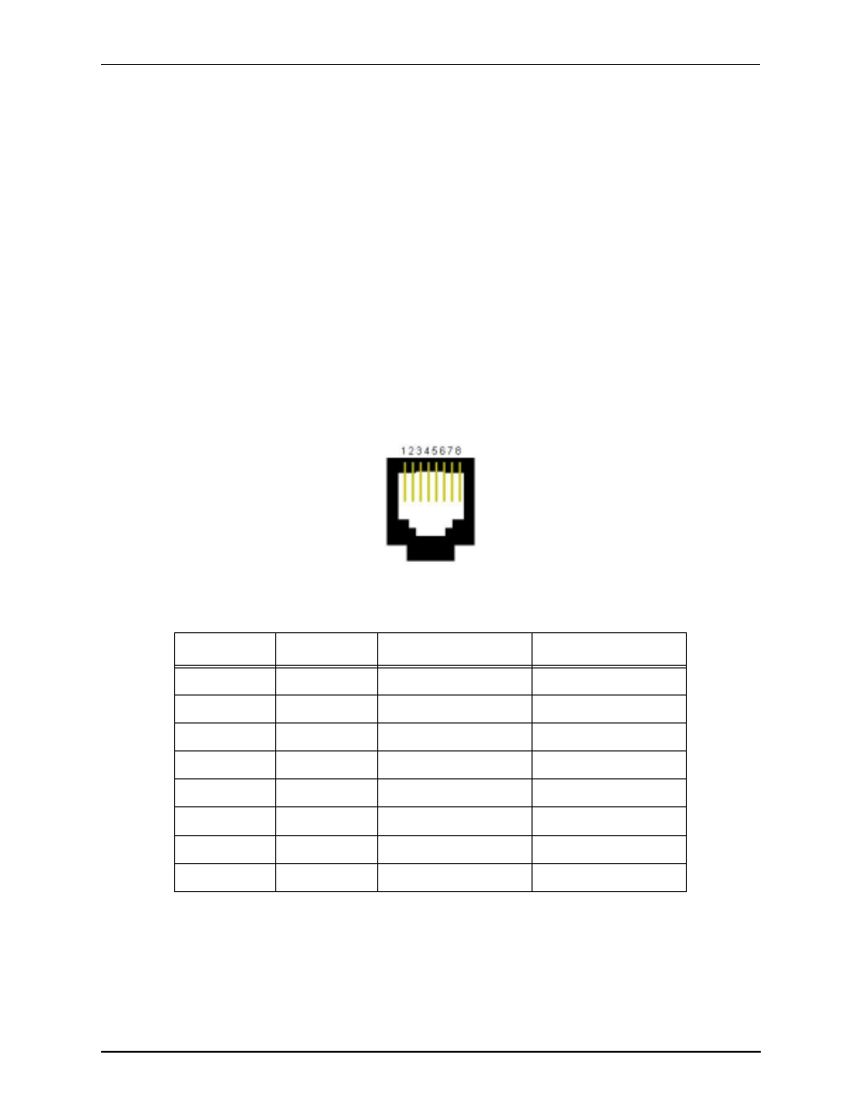
RJ-48 Input/Output ports. The eight RJ-48 connectors on the rear of the DS1 card (the transition module)
are used to provide network access; they route signals between the T1 or E1 and a piece of network equipment
(i.e., PBX or PSTN). The input/output signals are listed in Table 2-6.
Figure 2-21 RJ-48 Port Pin Order
Table 2-6 DS1 Signal for DS1Card - RJ-48 Ports
Ethernet port LEDs (rear view). Not available in current release.
Port#
Pin
Signal
Definition
1-8
1
RR -
Receive Ring
1-8
2
RT +
Receive Tip
1-8
3
N/C
Not Connected
1-8
4
TR -
Transmit Ring
1-8
5
TT +
Transmit Tip
1-8
6
N/C
Not Connected
1-8
7
N/C
No Connect
1-8
8
N/C
No Connect