7 cpld, 1 post code display, 2 bios protection – Endura RADISYS KP915GV User Manual
Page 94: 3 lan controller, 8 tpm, 9 normal, configure and recovery mode
KP915GV Product Manual
94
LED
State
Indicates
Blinking
yellow
The motherboard is in sleep state S1 with a message
waiting (as determined by ACPI TAPI).
4.7 CPLD
4.7.1 POST
Code
Display
Support for character-based LCD panel to display BIOS POST messages and other information.
Displays have an 8-bit parallel interface. Text for display is the BIOS Port 80 codes in the format:
"BIOS Code xx".
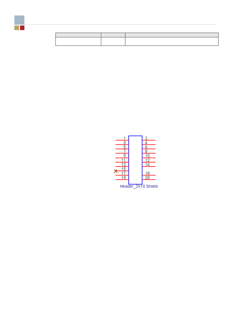
This section describes how the LCD character display support is implemented. With the exception
of the backlight power pins, the display connector is wired directly to the motherboard port GPIO
pins.
The logic in the CPLD is driven purely by software; there is no automatic generation of the interface
control signals. In this way, the use of the display is controlled exclusively by software (or BIOS).
The PWM signal from the CPLD requires an inverting low-pass filter in order to correctly drive the
contrast voltage to the display.
GPIO Header
4.7.2 BIOS
Protection
Support 2 GPIO pins to control the FWH pins TBL# (Top Block Lock) and WP# (Write Protect) to
protect the BIOS code
.
4.7.3 LAN
Controller
Support 2 GPIO pins to Enable/Disable on-board LAN1/LAN2 controller.
4.8 TPM
Pr-allocate 16 byte size I/O from 4700h for TPM module.
4.9
Normal, Configure and Recovery Mode
The motherboard can operate in one of three modes - Normal, Recovery and Configure by jumper
setting. Refer to section 1.4 (Configuration) for further information.