10 network – Endura RADISYS KP915GV User Manual
Page 29
KP915GV Product Manual
29
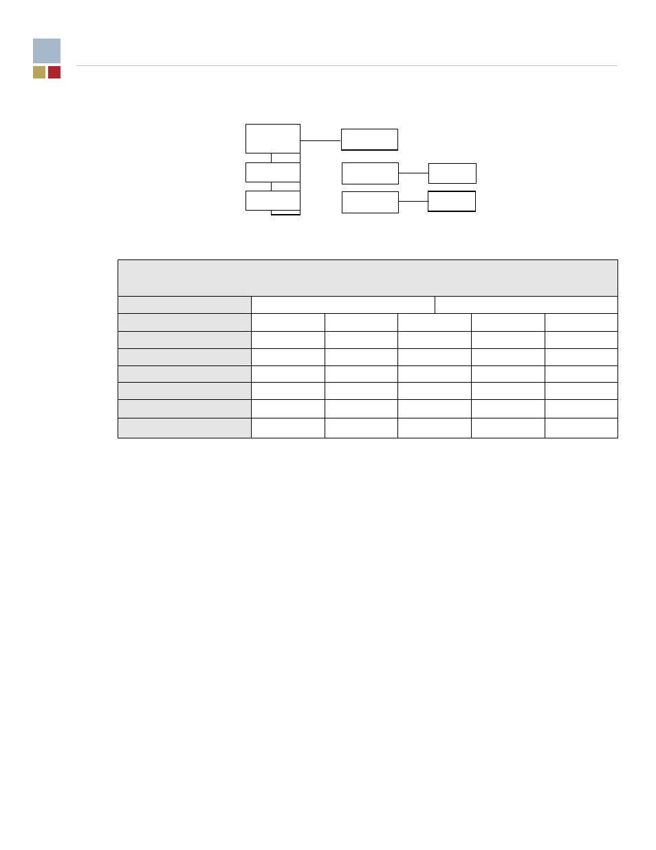
External
Internal
Figure 6.
Audio Jack Socket and ATAPI Connectors
* If a 3 jack external connector is needed, an option could be made available, for which the
added blue jack would be Line In, displacing the Line In black internal header (deleted) on
the standard configuration.
2.10 Network
•
One Ethernet controller configured as either 10/100 or 10/100/Gbit at build-time
•
Available with a second Ethernet controller configured as 10/100/Gbit
•
10/100Mbps Ethernet solution IEEE 802.3 10Base-T and 100Base-TX compatible
•
MAC integrated into ICH with Intel 82562GZ transceiver
•
Remote boot, PXE and Wake-On-LAN support
•
Gbit Ethernet solutions IEEE 802.3 10Base-T, 100Base-TX, 1000Base-T compatible
•
Intel 82573V (or ‘L) PCI Express Ethernet controller connected via I/O hub x1 lane
•
Full line-speed operation
•
Remote boot, PXE and Wake-On-LAN support
•
On-board RJ45 connector (RJ45 over dual USB connector) with two integral LEDs showing
combined link integrity and activity (yellow) plus line speed (green/amber)
•
Available with a second RJ45 over dual USB connector
Table 2: Audio Channel Allocation
I/O panel jack
Internal header
I/O panel jack color
Pink Lime Blue*
ATAPI header color
Black* White Yellow
Nominal function
Microphone
Line Out
Line In*
Microphone
Line Out
Line In capability
X X
Line Out capability
X X
Microphone capability
X X
Headphone Out Capability
X
ATAPI 3
ATAPI 2
ATAPI 1
Line out
Optional*
Line in
MIC in
Line out
MIC in