ProSoft Technology MVI56-PDPS User Manual
Page 61
Reference MVI56-PDPS
♦ ControlLogix Platform
Profibus DP Slave Communication Module
ProSoft Technology, Inc.
Page 61 of 88
April 22, 2008
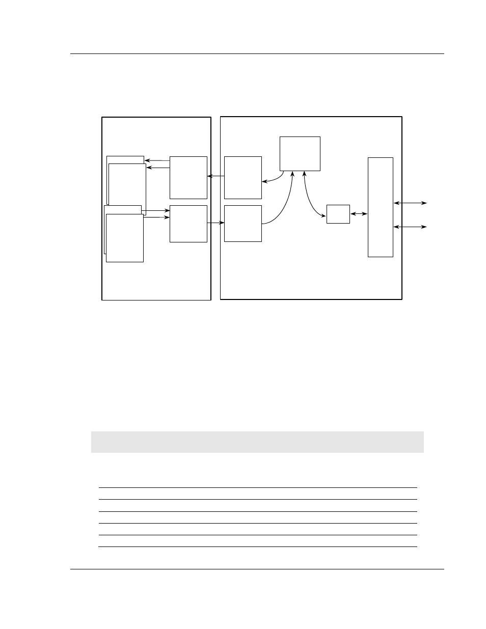
The following illustration shows the data transfer method used to move data
between the ControlLogix processor, the MVI56-PDPS module and the
PROFIBUS DP network.
PROFIBUS
DP Port
Driver
Slave
Driver
Logic
Module’s
Internal
Database
MVI56-PDPS Module
To
PROFIBUS
DP
NETWORK
Ladder
Logic
Transfers
Data from
module’s input
image to data
areas in the
processor
ControlLogix Processor
Controller Tags
ControlLogix Processor
Ladder
Logic
Transfers
Data from
Processor
data areas
to output image
Input Image
Output image
Back
p
lane
D
ri
ve
r
Status
Read Data
Write Data
Special Control
Blocks
As shown in the previous diagram, all data transferred between the module and
the processor over the backplane is through the input and output images. Ladder
logic must be written in the ControlLogix processor to interface the input and
output image data with data defined in the Controller Tags. All data used by the
module is stored in its internal database consisting of 200 registers for I/O and
Status information.
Data contained in this database is paged through the input and output images by
coordination of the ControlLogix ladder logic and the MVI56-PDPS module's
program. Up to 248 words of data can be transferred from the module to the
processor at a time. Up to 247 words of data can be transferred from the
processor to the module.
Note: Not all of the input and output images will contain PROFIBUS data.
The read and write block identification codes in each data block determine the
function to be performed or the content of the data block. The block identification
codes used by the module are listed in the following table:
Block Range
Descriptions
-1
Null block
0 to 1
Read or write data
9998
Warm-boot control block
9999
Cold-boot control block