ProSoft Technology MVI56-PDPS User Manual
Page 13
Start Here
MVI56-PDPS ♦ ControlLogix Platform
Profibus DP Slave Communication Module
ProSoft Technology, Inc.
Page 13 of 88
April 22, 2008
Warning: When you insert or remove the module while backplane power is on, an electrical arc
can occur. This could cause an explosion in hazardous location installations. Verify that power is
removed or the area is non-hazardous before proceeding. Repeated electrical arcing causes
excessive wear to contacts on both the module and its mating connector. Worn contacts may
create electrical resistance that can affect module operation.
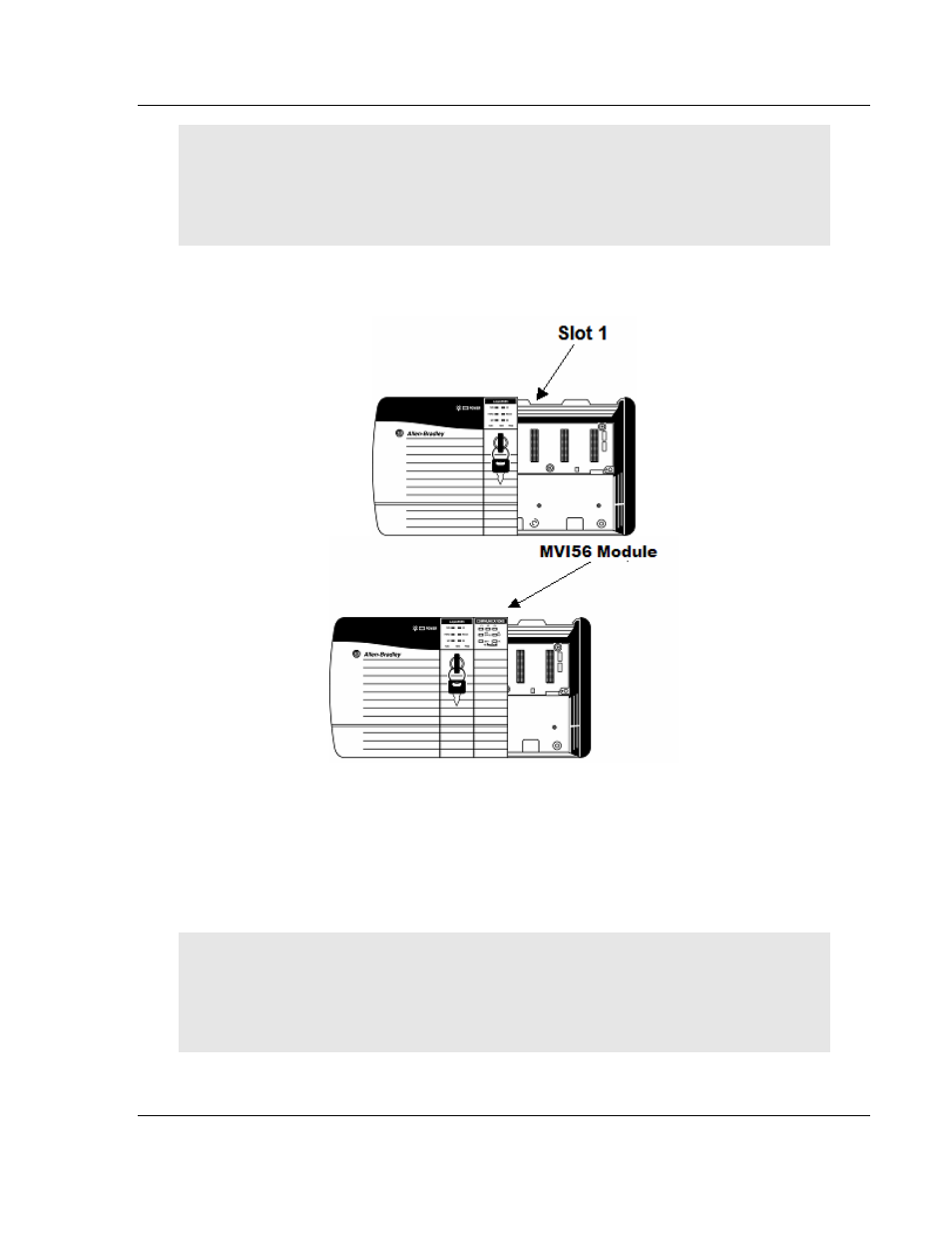
1
Turn power OFF.
2
Align the module with the top and bottom guides, and slide it into the rack
until the module is firmly against the backplane connector.
3
With a firm but steady push, snap the module into place.
4
Check that the holding clips on the top and bottom of the module are securely
in the locking holes of the rack.
5
Make a note of the slot location. You will need to identify the slot in which the
module is installed in order for the sample program to work correctly. Slot
numbers are identified on the green circuit board (backplane) of the
ControlLogix rack.
6
Turn power ON.
Note: If you insert the module improperly, the system may stop working, or may behave
unpredictably.
Note: If you are installing MVI56-PDPS with other modules connected to the PCI bus, the
peripheral modules will not have holding clips. Make sure all of the modules are aligned with their
respective slots before you snap them into place.