Setting jumpers, Install the module in the rack, Setting – ProSoft Technology MVI56-PDPS User Manual
Page 12: Jumpers
MVI56-PDPS ♦ ControlLogix Platform
Start Here
Profibus DP Slave Communication Module
Page 12 of 88
ProSoft Technology, Inc.
April 22, 2008
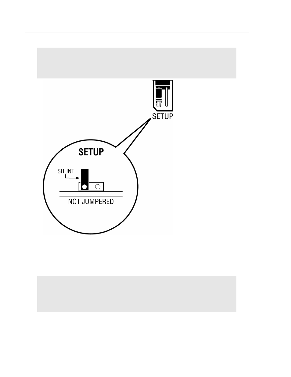
1.4 Setting
Jumpers
Note: The Setup Jumper acts as "write protection" for the module's flash memory. In "write
protected" mode, the Setup pins are not connected, and the module's firmware cannot be
overwritten. Do not jumper the Setup pins together unless you are directed to do so by ProSoft
Technical Support.
1.5
Install the Module in the Rack
If you have not already installed and configured your ControlLogix processor and
power supply, please do so before installing the MVI56-PDPS module. Refer to
your Rockwell Automation product documentation for installation instructions.
Warning: You must follow all safety instructions when installing this or any other electronic
devices. Failure to follow safety procedures could result in damage to hardware or data, or even
serious injury or death to personnel. Refer to the documentation for each device you plan to
connect to verify that suitable safety procedures are in place before installing or servicing the
device.
After you have checked the placement of the jumpers, insert MVI56-PDPS into
the ControlLogix chassis. Use the same technique recommended by Rockwell
Automation to remove and install ControlLogix modules.