1 basic command set functions, 2 plc-5 command set functions – ProSoft Technology MVI56-DFCM User Manual
Page 92
Reference
MVI56-DFCM ♦ ControlLogix Platform
User Manual
DF1 Half/Full Duplex Master/Slave Serial Communication Module
Page 92 of 106
ProSoft Technology, Inc.
September 24, 2014
Module Information Data
Device Information Data
Col #
1
2
3
4
5
6
7
8
9
10
11
Functio
n Code
Enabl
e
Code
Internal
Addres
s
Poll
Interval
Time
Coun
t
Swa
p
Code
Node
Addres
s
Functio
n Code
Function Parameters
FC 5
Code
Register Second
s
Count Code Node
5
Word
Addres
s
FC 100
Code
Register Second
s
Count Code Node
100
File
Number
Elemen
t
Sub-
Element
FC 101
Code
Register Second
s
Count Code Node
101
File
Number
Elemen
t
Sub-
Element
FC 102
Code
Register Second
s
Count 0
Node
102
File
Number
Elemen
t
Sub-
Element
FC 501
Code
Register Second
s
Count Code Node
501
File
Type
File
Number
Element
FC 502
Code
Register Second
s
Count Code Node
502
File
Type
File
Number
Element Sub-
Element
FC 509
Code
Register Second
s
Count Code Node
509
File
Type
File
Number
Element
FC 510
Code
Register Second
s
Count Code Node
510
File
Type
File
Number
Element Sub-
Element
FC 511
Code
Register Second
s
Count 0
Node
511
File
Type
File
Number
Element Sub-
Element
Node Address = Destination Address for Message
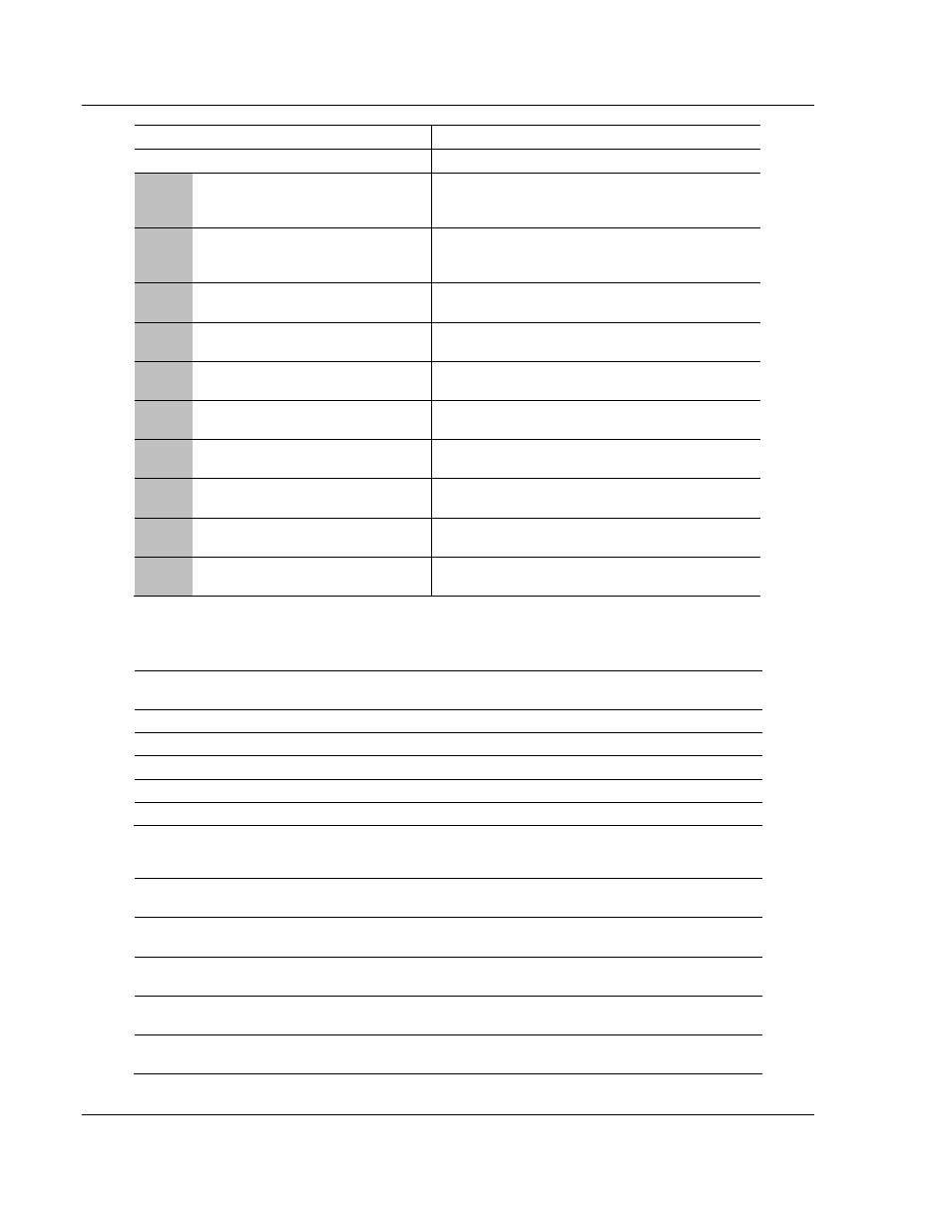
5.3.1 Basic Command Set Functions
Function
Code
Comman
d
Function Definition
PLC5
SLC500 &
MicroLogix
Power-
monitor II
ControlLogix
1
0x00
N/A
Protected Write
X
X
2
0x01
N/A
Unprotected Read
X
X
X
3
0x02
N/A
Protected Bit Write
X
X
4
0x05
N/A
Unprotected Bit Write X
X
5
0x08
N/A
Unprotected Write
X
X
X
5.3.2 PLC-5 Command Set Functions
Function
Code
Command Function Definition
PLC5
SLC500 &
MicroLogix
Power-
monitor II
ControlLogix
100
0x0F
0x00
Word Range Write
(Binary Address)
X
X
101
0x0F
0x01
Word Range Read
(Binary Address)
X
X
102
0x0F
0x26
Read-Modify-Write
(Binary Address)
X
X
150
0x0F
0x00
Word Range Write
(ASCII Address)
X
X