ProSoft Technology MVI56-DFCM User Manual
Page 72
Reference
MVI56-DFCM ♦ ControlLogix Platform
User Manual
DF1 Half/Full Duplex Master/Slave Serial Communication Module
Page 72 of 106
ProSoft Technology, Inc.
September 24, 2014
After the module has received the Module Configuration Block from the
processor, the module will begin communicating with other nodes on the
network, depending on the configuration.
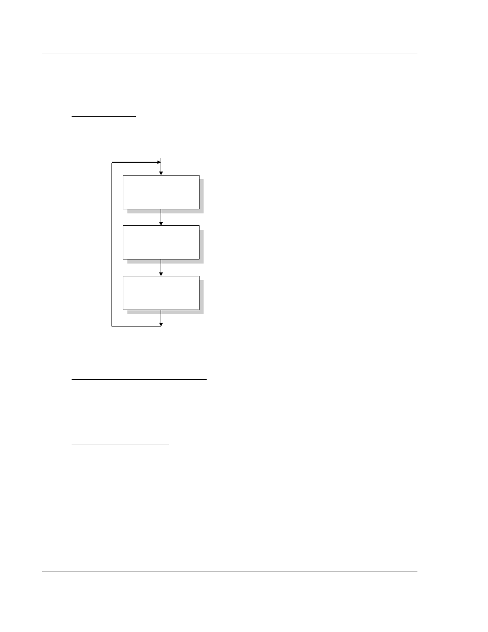
Main Logic Loop
Upon completing the power up configuration process, the module enters an
infinite loop that performs the following functions:
Call I/O Handler
Call CFG/DEBUG Port
Driver
Call Network Master &
Slave Drivers
Call I/O Handler
Transfers data between the module and processor
(user, status, etc.)
Call Serial Port Driver
Rx and Tx buffer routines are interrupt driven. Call to
serial port routines check to see if there is any data
in the buffer, and depending on the value, will either
service the buffer or wait for more characters.
Call Network Master & Slave Drivers
Generate messages and
respond to messages received.
From Power Up Logic
ControlLogix Processor Not in Run
Whenever the module detects that the processor has gone out of the Run mode
(that is, Fault or PGM), the DF1 ports can be shut down as prescribed in the user
configuration. When the processor is returned to a running state, the module will
resume communications on the network.
Backplane Data Transfer
The MVI56-DFCM module communicates directly over the ControlLogix
backplane. Data is paged between the module and the ControlLogix processor
across the backplane using the module's input and output images. The update
frequency of the images is determined by the scheduled scan rate defined by the
user for the module and the communication load on the module. Typical updates
are in the range of 2 to 10 milliseconds.