ProSoft Technology MVI56-DFCM User Manual
Page 74
Reference
MVI56-DFCM ♦ ControlLogix Platform
User Manual
DF1 Half/Full Duplex Master/Slave Serial Communication Module
Page 74 of 106
ProSoft Technology, Inc.
September 24, 2014
All data transferred between the module and the processor over the backplane is
through the input and output images. Ladder logic must be written in the
ControlLogix processor to interface the input and output image data with data
defined in the Controller Tags. All data used by the module is stored in its internal
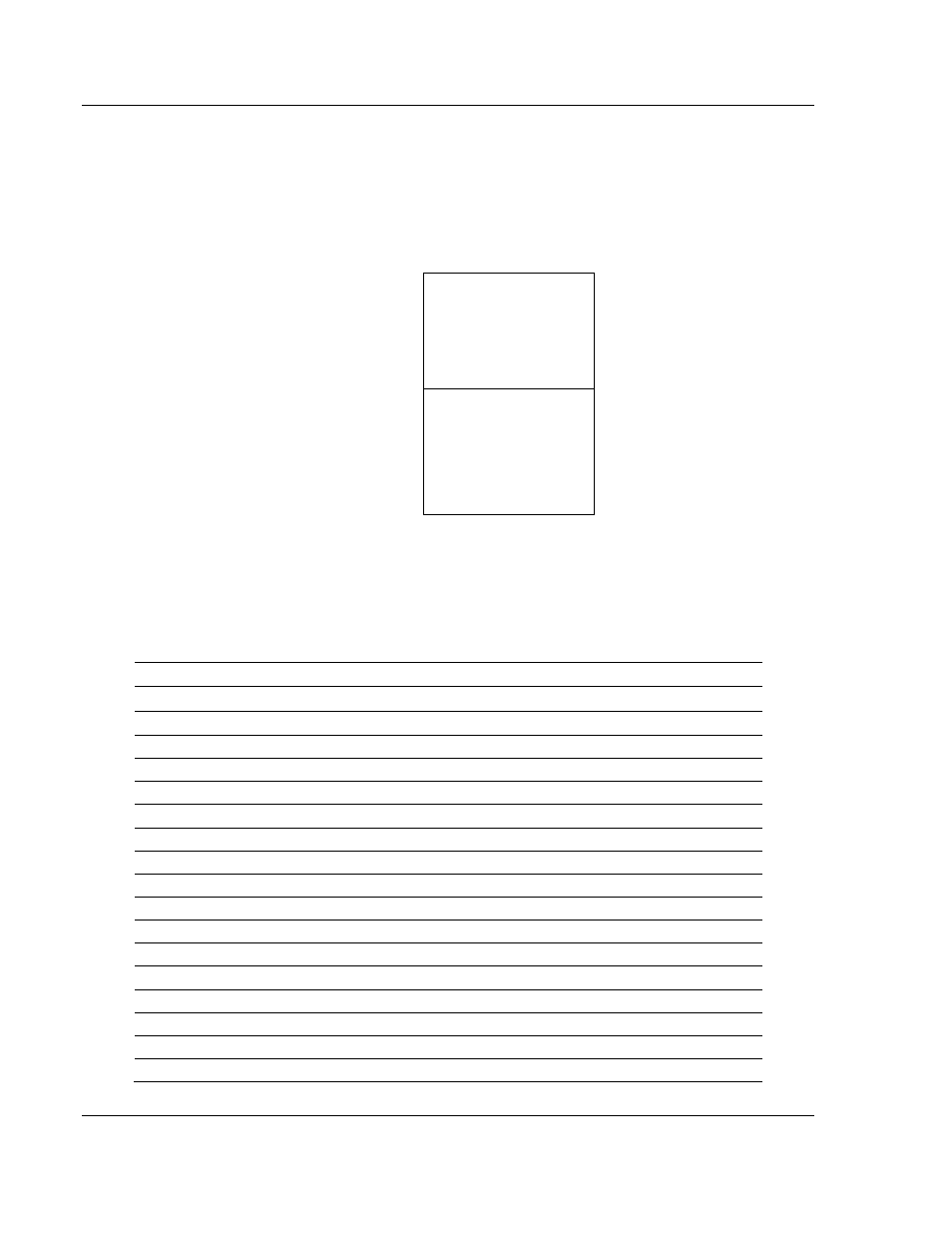
database. The following illustration shows the layout of the database:
Module’s Internal Database Structure
5000 registers for user data
0
Register Data
4999
3400 words of configuration and
status data
5000
Status and Config
8399
Data contained in this database is paged through the input and output images by
coordination of the ControlLogix ladder logic and the MVI56-DFCM module's
program. Up to 248 words of data can be transferred from the module to the
processor at a time. Up to 247 words of data can be transferred from the
processor to the module. The read and write block identification codes in each
data block determine the function to be performed or the content of the data
block. The block identification codes used by the module are listed below:
Block Range
Descriptions
-9000
Configuration data (sent from module)
-7100
Port 2 Override File Maps (sent from module)
-7000
Port 1 Override File Maps (sent from module)
-6100 to -6104
Port 2 commands (sent from module)
-6000 to -6004
Port 1 commands (sent from module)
-1
Null block
0
Null block
1 to 999
Read or write data
1000
Event Port 1
2000
Event Port 2
3000 to 3001
Port 1 slave polling control
3002 to 3003
Port 1 slave status
3100 to 3101
Port 2 slave polling control
3102 to 3103
Port 2 slave status
5000 to 5006
Port 1 command control
5100 to 5106
Port 2 command control
6000 to 6004
Port 1 commands (sent to module)