Rs-422 – ProSoft Technology MVI56-LTQ User Manual
Page 71
MVI56-LTQ ♦ ControlLogix Platform
Reference
Limitorque Valve Actuator Master Communication Module
User Manual
ProSoft Technology, Inc.
Page 71 of 98
August 30, 2010
5.3.3 Network Cable Connection to Limitorque RS-232/RS-485
Converters
For the RS-485 connection, the network cable is connected to the converter via a
three-pin or five-pin removable connector (depending on the converter model).
This connector is located on the rear of the converter. Prepare the cable as
detailed in the Limitorque Accutronix MX/DDC-100 Field Unit Installation and
Operation Manual
Self-Steering Converter – P/N 61-825-1032-4
Pin
Function
Wire Color
1
DATA
White
2
DATA* (see note 1)
Blue
3
Earth ground (see note 2)
Shield
Note 1: Indicates negative side of signal.
Note 2: Must be connected to earth ground to assure surge protection.
Steered Converter – P/N 61-825-0966-4
Pin
Function
Wire Color
1
DATA
White
2
DATA* (see note 1)
Blue
3
Earth ground (see note 2)
Shield
4
Not Used
Not Used
5
Not Used
Not Used
Note 1: Indicates negative side of signal.
Note 2: Must be connected to earth ground to assure surge protection.
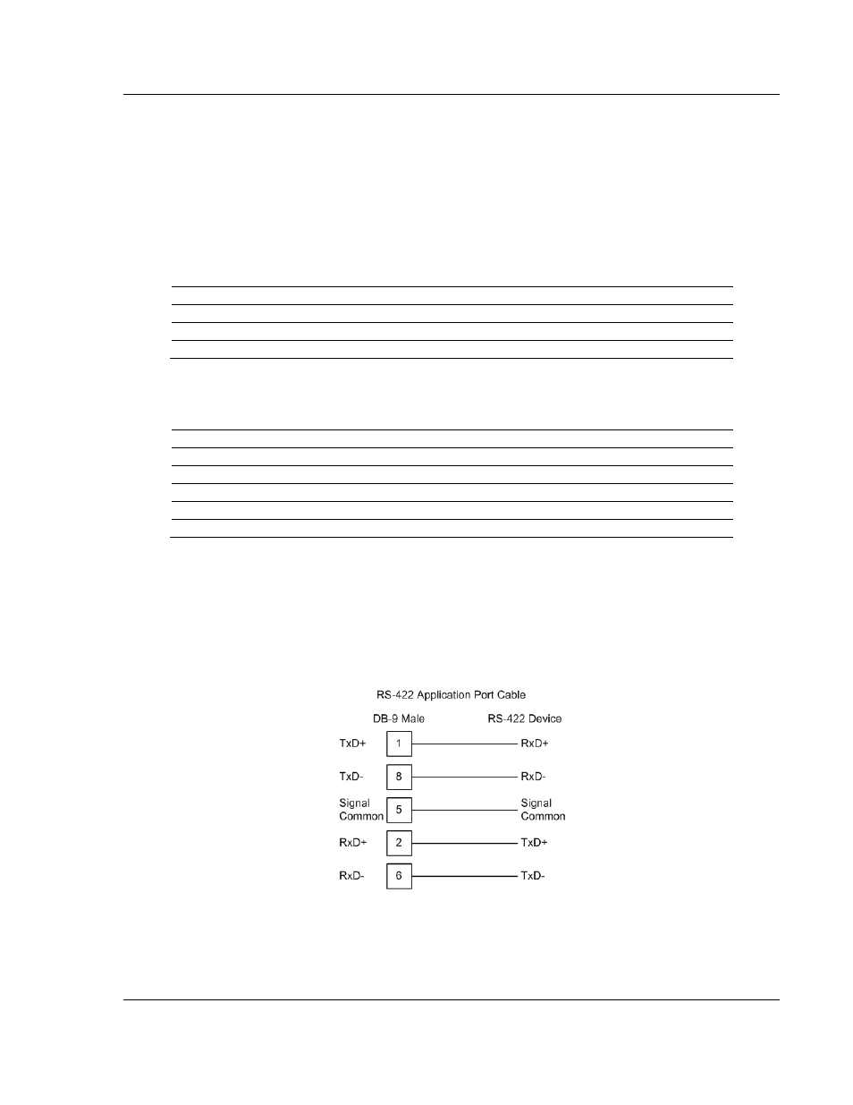
5.3.4 RS-422
The RS-422 interface requires a single four or five wire cable. The Common
connection is optional, depending on the RS-422 network devices used. The
cable required for this interface is shown below: