ProSoft Technology MVI56-LTQ User Manual
Page 60
Reference
MVI56-LTQ ♦ ControlLogix Platform
User Manual
Limitorque Valve Actuator Master Communication Module
Page 60 of 98
ProSoft Technology, Inc.
August 30, 2010
Data contained in this database is paged through the input and output images by
coordination of the ControlLogix ladder logic and the MVI56-LTQ module's
program. Up to 248 words of data can be transferred from the module to the
processor at a time. Up to 247 words of data can be transferred from the
processor to the module. The read and write block identification codes in each
data block determine the function to be performed or the content of the data
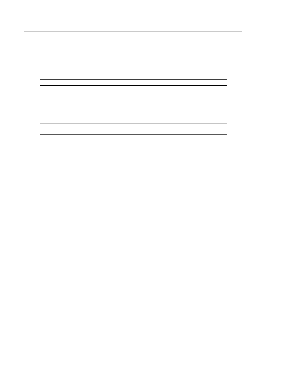
block. The block identification codes used by the module are listed below:
Block Number
Description
0
On read, this block contains the valve information for slaves 1 to 20. For the
write operation, this block contains the digital command control data.
1
On read, this block contains the valve information for slaves 21 to 40. For the
write operation, this block contains the analog command control data.
2 to 7
These blocks are only used for the read operation. They contain valve data for
up to 20 slave units.
9000
This is the configuration data block transferred from the processor
9998
This block is sent from the processor to the module to instruct the module to
perform the warm-boot operation.
9999
This block is sent from the processor to the module to instruct the module to
perform the cold-boot operation.
Each image has a defined structure depending on the data content and the
function of the data transfer.