ProSoft Technology MVI56-LTQ User Manual
Page 59
MVI56-LTQ ♦ ControlLogix Platform
Reference
Limitorque Valve Actuator Master Communication Module
User Manual
ProSoft Technology, Inc.
Page 59 of 98
August 30, 2010
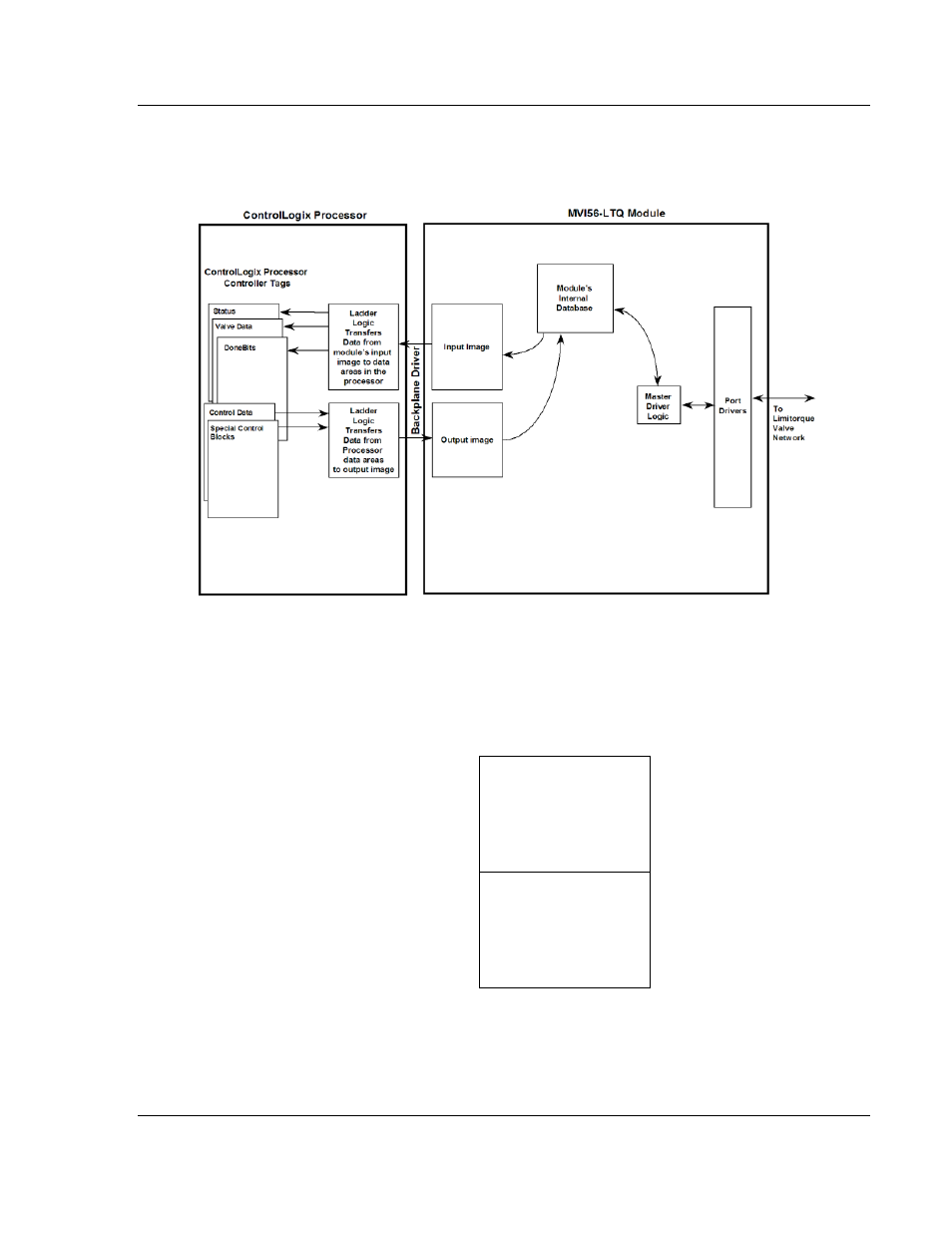
The following illustration shows the data transfer method used to move data
between the ControlLogix processor, the MVI56-LTQ module and the Limitorque
valve network.
All data transferred between the module and the processor over the backplane is
through the input and output images. Ladder logic must be written in the
ControlLogix processor to interface the input and output image data with data
defined in the Controller Tags. All data used by the module is stored in its internal
database. The following illustration shows the layout of the database:
Module’s Internal Database Structure
1500 registers for user data
0
Register Data
1499
2500 words of control data
1500
Control Data
3999
- ILX69-PBS (102 pages)
- MVI69E-LDM (130 pages)
- ILX69-PBM (124 pages)
- MVI69L-MBTCP (152 pages)
- PS69-DPS (108 pages)
- MVI69E-MBTCP (150 pages)
- MVI69L-MBS (154 pages)
- MVI69E-MBS (162 pages)
- PS69-DPM (130 pages)
- MVI69-FLN (137 pages)
- MVI69-DFNT (167 pages)
- MVI69-GEC (86 pages)
- MVI69-PDPS (96 pages)
- MVI46-S3964R (80 pages)
- MVI46-S3964R (78 pages)
- MVI46-DNPSNET (119 pages)
- MVI69-ADMNET (122 pages)
- MVI56-104S (188 pages)
- MVI69-ADM (342 pages)
- MVI69-MCM (167 pages)
- 5307-MBP-HART (169 pages)
- MVI69-PDPMV1 (225 pages)
- MVI69-GSC (102 pages)
- MVI69-DNP (129 pages)
- MVI69-DFCM (117 pages)
- MVI69-103M (131 pages)
- PC56-OPC (34 pages)
- MVI46-MBP (101 pages)
- MVI69-101S (149 pages)
- MVI56-103M (152 pages)
- MVI56-DFCMR (113 pages)
- MVI56-DNP (193 pages)
- ILX56-MM (112 pages)
- MVI56-BAS (234 pages)
- MVI56-DFCM (106 pages)
- MVI46-PDPS (88 pages)
- MVI56E-MNETCR (159 pages)
- MVI46-AFC (316 pages)
- MVI56E-MNETC (183 pages)
- MVI56E-GSC/ GSCXT (140 pages)
- MVI56-PDPMV1 (255 pages)
- MVI46-MNETC (153 pages)
- CLX-APACS (53 pages)
- MVI56E-MNET/MNETXT (181 pages)