ProSoft Technology MVI56-LTQ User Manual
Page 67
MVI56-LTQ ♦ ControlLogix Platform
Reference
Limitorque Valve Actuator Master Communication Module
User Manual
ProSoft Technology, Inc.
Page 67 of 98
August 30, 2010
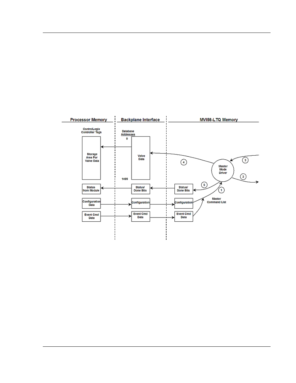
5.2.2 Data Flow Between MVI56-LTQ Module and ControlLogix
Processor
The following topics describe the flow of data between the two pieces of
hardware (ControlLinx processor and the MVI56-LTQ module) and nodes on the
Limitorque valve network. In the Master mode, the MVI56-LTQ module is
responsible for issuing read or write commands to slave devices on the
Limitorque valve network. These commands are generated from a fixed set of
commands contained in the module. The module issues the read commands
continuously. Write commands are issued under ladder logic control. The
following flow chart and associated table describe the flow of data into and out of
the module.
1 The module obtains configuration data from the ControlLogix processor. This
configuration completely defines the operation parameters for the module.
2 After configuration, the module begins transmitting read commands to the
valves on the network. If an event command (a bit in one of the digital control
word arrays is set) is recognized by the module, it will issue the associated
write command to the valve. The done bit for the event will be set in the
DoneBit array.
3 Presuming successful processing by the node specified in the command, a
response message is received into the driver for processing.
4 Data received from the node on the network is passed into the module’s
internal database (only for read function messages).
5 Status and done bit array data is returned to the ControlLogix processor.
Refer to Module Configuration (page 21) for a complete description of the
parameters required for configuration of the module.