ProSoft Technology ILX69-PBS User Manual
Page 53
ILX69-PBS ♦ CompactLogix or MicroLogix Platform
Contents
PROFIBUS Slave Communication Module
User Manual
ProSoft Technology, Inc.
Page 53 of 102
March 20, 2015
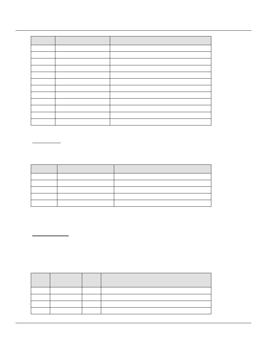
Offset
Register Type
Name
18 to 19
Slave Status Information
TaskState
20 to 21
Slave Status Information
InputDataLen
22 to 23
Slave Status Information
OutputDataLen
24 to 25
Slave Status Information
ErrorCount
26
Slave Status Information
LastError
27
Slave Status Information
Reserved
28 to 29
Slave Status Information
WatchdogTime
30 to 31
Slave Status Information
IrqCounter
32 to 37
Slave Status Information
Dpv1StatusRegister
38 to 39
Slave Status Information
Reserved
40 to 135
Slave Status Information
ExtStatusInfo[96]
136 to 379
PROFIBUS Output Area
PBOutputData
Output Array
Below is a summary of the register layout of the output area of the ILX69-PBS. The offset
values are defined in bytes.
Offset
Register Type
Name
0
Device Command Register
Command Bits
1
Device Command Register
Reserved
2
Device Command Register
Reserved
3
Device Command Register
ExtStaSelect
4 to 248
PROFIBUS Input Area
PBInputData, 244 bytes
6.2.2 Input Array
Status Registers
The ILX69-PBS uses the first 4 bytes of the PLC input area to transfer device status register
information. The Status Registers contain the ILX69-PBS communication status and
command status. The mapping is shown in the table below.
Device State Register
Byte
Offset
Structure
Member
Data
Type
Description
0
MSB
SINT
Module Status Bits, see table below
1
Reserved
SINT
Reserved
2
BTO
SINT
Block Transfer Out
3
BTI
SINT
Block Transfer In