Node b (called node) configuration, Mlppp point-to-point configurations, Dial-in router example – Enterasys Networks Security Router X-PeditionTM User Manual
Page 253: Node b (called node) configuration -31, Mlppp point-to-point configurations -31, Dial-in router example -31
Configuring DoD/BoD
XSR User’s Guide 10-31
Node B (Called Node) Configuration
The following commands add a dialer pool member with the Central Office switch type to BRI
interface 1/0:
XSR(config)#interface bri 1/0
XSR(config-if
XSR(config-if
XSR(config-if
The commands below add a dialer pool and enable MLPPP on Dialer port 1:
XSR(config)#interface dialer 1
XSR(config-if
XSR(config-if
XSR(config-if
XSR(config-if
XSR(config-if
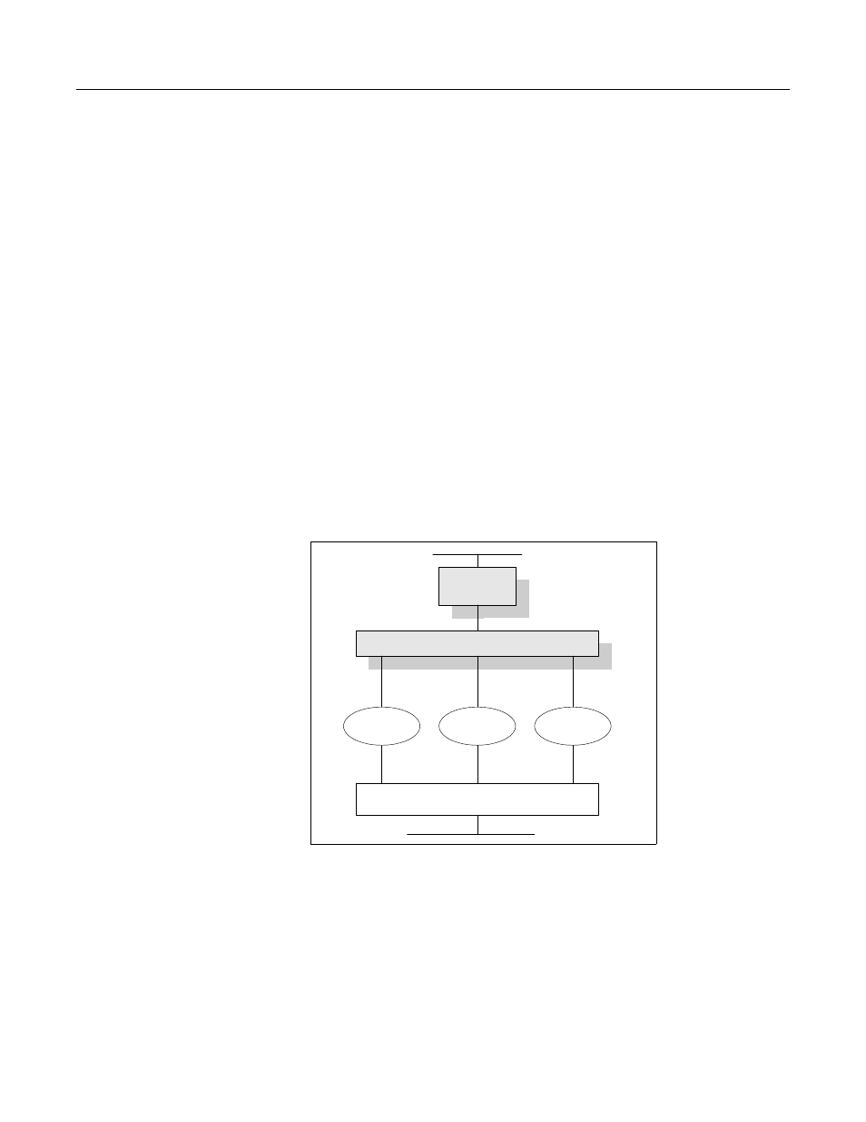
MLPPP Point-to-Point Configurations
The following MLPPP point-to-point topology can be used for Bandwidth on Demand
applications, as illustrated by
. This example creates three switched lines linking users
on XSR-Toronto’s network with those on XSR-Andover’s network.
Figure 10-14 MLPPP Point-to-Point Topology
Dial-in Router Example
The following commands add a dialer pool and configure Multilink PPP on XSR-Toronto’s Dialer
interface 1:
XSR(config)#interface dialer 1
XSR(config-if
XSR(config-if
XSR(config-if
.
XSR-Andover
Switched
line
Switched
line
XSR-
Toronto
Switched
line
MLPPP
172.22.85.1
172.22.80.4
172.22.85.2
172.22.95.2