Example 2: view a signal delay caused by a circuit – RIGOL DS1000B User Manual
Page 140

RIGOL
User’s Guide for DS1000B Series
3-2
Example 2: View a Signal Delay Caused by a Circuit
This example is to test the input and output signals of a circuit and observe the
signal delay. First, set the probe
[1]
and the channel attenuation to 10X and connect
CH1 probe to the input, CH2 to the output of the circuit. Do these steps as follow:
1. Display the signals (CH1 and CH2):
(1) Press the Auto button.
(2) Adjust the vertical and the horizontal scale by turning the
knobs to
set appropriate ranges for display.
(3) Press the CH1 button to select Channel 1, and turn the vertical
knob to adjust the vertical position of Channel 1 waveform.
(4) Press the CH2 button to select Channel 2, and turn the vertical
knob to adjust the vertical position of Channel 2 waveform.
2. Measure the delay time when a signal going through the circuit.
Auto-measuring the delay:
Press Measure→Source→CH1 to set the measurement source.
Press Time to select the measurement Type.
Press Delay A→B to display the result on the screen.
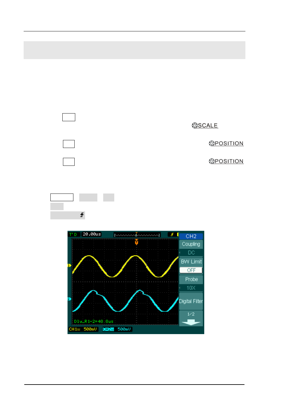
You can see the change of the waveform in the following figure:
Figure 3-1 Waveform distortion
Note:
[1] For DS1204B, the standard probe is RP3300A which attenuation ratio is fixed at 10X and does
not need to be adjusted.
