MCZ PowerTherm User Manual
Page 26
Chapter 3
INSTALLATION AND USE MANUAL
page
26
Installation and fitting
Technical service - Rights reserved MCZ S.p.A. - Reproduction prohibited
We recommend making the hood liner in fire-resistant
plasterboard of 15/20 mm. thickness, with a self-supporting frame in
galvanised profile, so as not put weight on components of the cladding
(such as wooden beams and marble architraves) which do not have a
load-bearing structure and to make it easy to work in the event of
future anomalies and/or maintenance.
Dry install the fire bed of the cladding, leaving an aperture of 1 cm
between the fireplace stove and the fire bed to provide insulation.
3.13. INSULATING A WOODEN BEAM
The wood beam must be protected with adequate insulation from
heated parts to prevent the risk of fire or damage of the cladding.
3.14. INSTALLATION OF STANDARD MCZ CLADDING
For the installation of cladding specifically designed for the MCZ
PowerTherm, the installer should refer to the use and installation
manual included with each specific cladding.
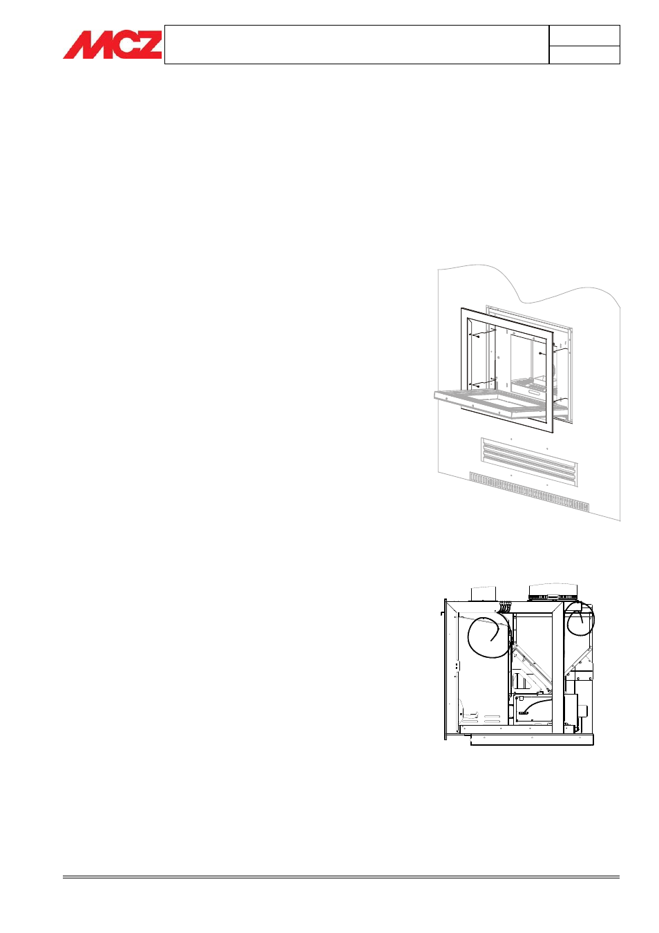
3.15. COMPENSATION FRAME ASSEMBLY
Once the cladding and/or the part in plasterboard are complete, install
the previously removed compensation frame(
chap. 3.5)
This frame is designed to finish and cover the crack that is formed
between the metal structure of the unit and the wall.
To assemble the frame, just open the PowerTherm door, fit the frame
as shown in the figure and use the four screws provided to fix it onto
the stiles of the structure, inside the profile of the door.
3.16. INSTALLATION OF PELLET CHUTE DOOR AND
CONTROL PANELS
The pellet loading door arrives from the factory without the emergency
panel and serial connectors panel, these must be assembled after
having decided the opening direction of the door.
The door can be rotated by 180° depending on whether it is positioned
on the left or right side of the cladding. In fact, the door frame is
perfectly symmetric with regard to the holes for fastening the door to
the hood, so it can be rotated as needed.
It should be noted, however, that the holes for housing the panels are
different from one another and each panel must be assembled only and
exclusively in its own housing. According to the direction of the door,
the emergency panel is located above the main switch or vice versa.
Position 1 = wired main switch
Position 2= wired emergency panel
2
1
Compensation frame assembly