A1 2 3 – MCZ PowerTherm User Manual
Page 16
Chapter 3
INSTALLATION AND USE MANUAL
page
16
Installation and fitting
Technical service - Rights reserved MCZ S.p.A. - Reproduction prohibited
3.4.
INSTALLING THE LEG KIT (OPTIONAL) AND
FASTENING THE UNIT TO THE FLOOR
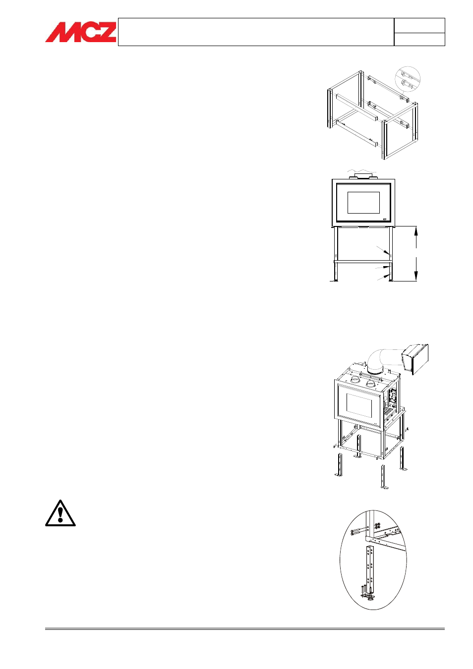
The kit is delivered dismantled in one pack; remove the protective
nylon being careful not to throw away the small bags with screws in
supplied for assembly.
The first operation to be carried out is that of assembling the 2
prewelded side element with the 4 crosspieces supplied using the self-
drilling hexagon headed bolts. The crosspieces must be attached
using all of the screws provided.
The second operation is that of choosing at which height to attach the
unit support legs.
The legs have two holes at three different heights. The support
structure has two holes that coincide with those on the legs.
The choice of holes determines the height of the compensation frame
above the ground.
If you use the first holes on the legs starting from the top, the height
of the frame will be 700 mm. If you use the middle holes, the height
will be 600 mm. If you use the lowest holes, the height will be 500 mm
(see figure)
Once you have selected the holes and the height, use the bolts and
nuts to firmly attach the legs.
The legs must be attached using all of the screws provided.
Place the unit onto the frame and lock it in place using all the cross
head screws supplied.
Once the kit has been assembled, precisely define the final position for
the unit and adjust the level using the adjustable feet.
Adjust the feet as follows:
x
Turn the feet clockwise to lower the unit
x
Turn the feet counter-clockwise to raise the unit
After adjusting the feet, anchor the unit to the floor with the brackets
that were previously installed on the feet.
You must anchor the unit to the floor because during annual
maintenance by an authorized technician, the combustion chamber may
be removed from its seat via the two extensible guides.
In this situation, the centre of balance of the unit moves forward
significantly. If the product has not been anchored to the floor, it may
lose stability.
To attach the legs to the floor, use expansion plugs and 6 or 8 mm
screws(“Fischer” type or similar)
The unit must be attached to the ground.
MCZ shall not be held liable for damage to persons or
things if this warning is disregarded.
Assembly of feet and anchoring brackets
Selection of holes and therefore of final height
1.
A = 700 mm
2.
A = 600 mm
3.
A = 500 mm
A
1
2
3
Assembly of support legs