13 2 4 a a b c – MCZ PowerTherm User Manual
Page 21
Chapter 3
INSTALLATION AND USE MANUAL
page
21
Installation and fitting
Technical service - Rights reserved MCZ S.p.A. - Reproduction prohibited
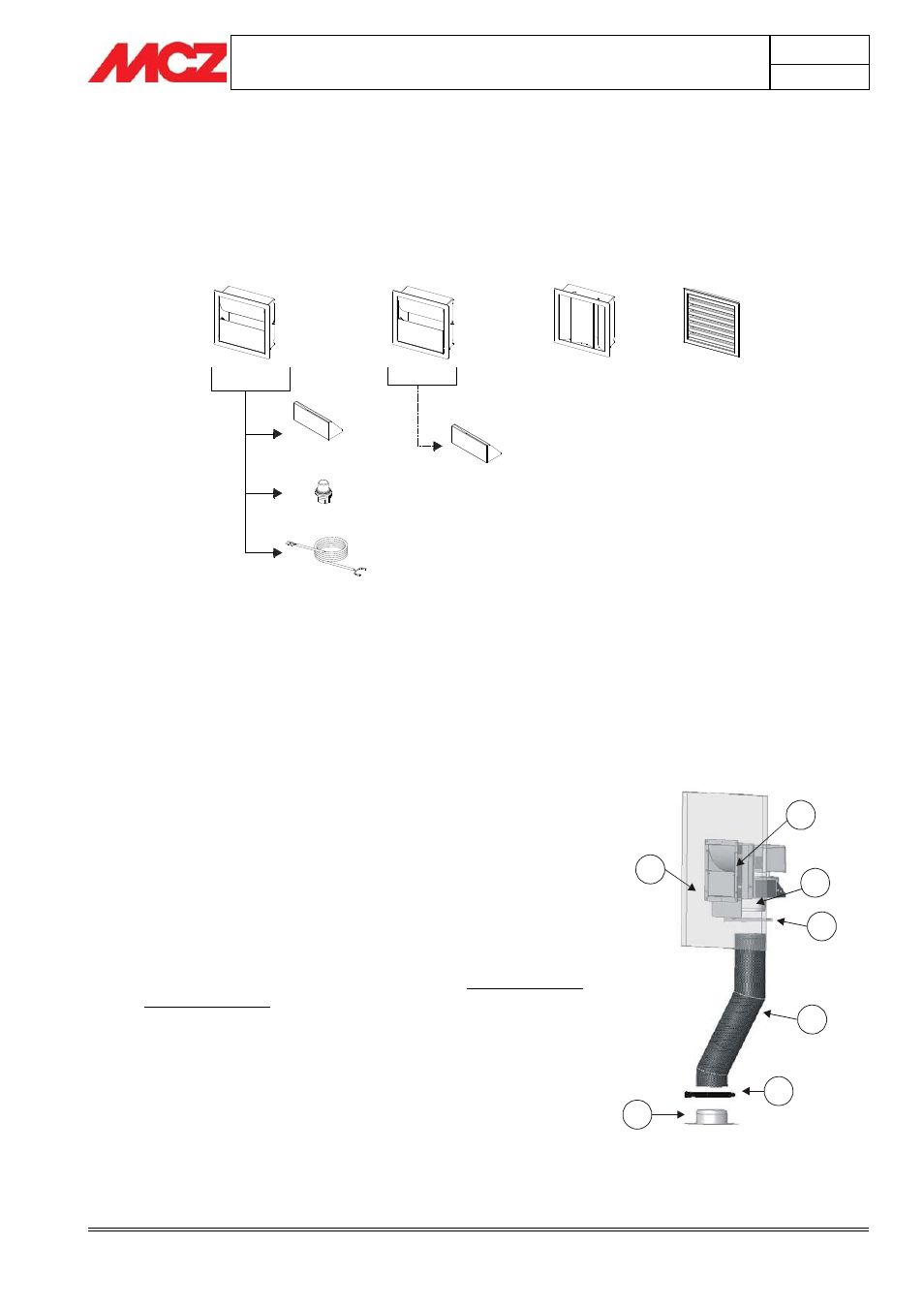
3.10.2.
Vents applicable to the Forced
Ventilation kit
1
3
2
4
A
A
B
C
1) Monodirectional air vent
A) Tray
B) Light
C) Silicon light wiring
2) Monodirectional air vent
A) Tray
3) Bidirectional air vent
4) Multidirectional air vent (supplied).
3.10.3.
INSTALLING THE FORCED VENTILATION
KIT
Before installing the natural or forced ventilation kit, make sure you
have the following material available (fig.1):
1) Connect the flanges (d) located in the upper part of unit and
the pipesa) using the supplied ties (b).
2) On the wall, prepare (f) at the desired height (recommended at
2 m from the floor) two holes for the hot air outlet equal to 185
x 185 mm.
3) Insert the structure of the selected outlet (g), within the holes
185 x 185 mm, working from the outside towards the inside of
the wall.
4) On the inner part of the wall, at the point where the outlet
structure is (1), fix the fastening bracket group (2), using the
four screws and nuts (3) in supplied (fig.2).
5) Connect the hose (a), previously fixed to the unit, to the joint
(e) located on the outlet structure.
6) Tighten the hose to the joint using the supplied tie (c).
a
b
d
c
f
g
e
Figure 1– Hose connection