Option error codes, Option compatibility – Yaskawa SI-EN3D User Manual
Page 62
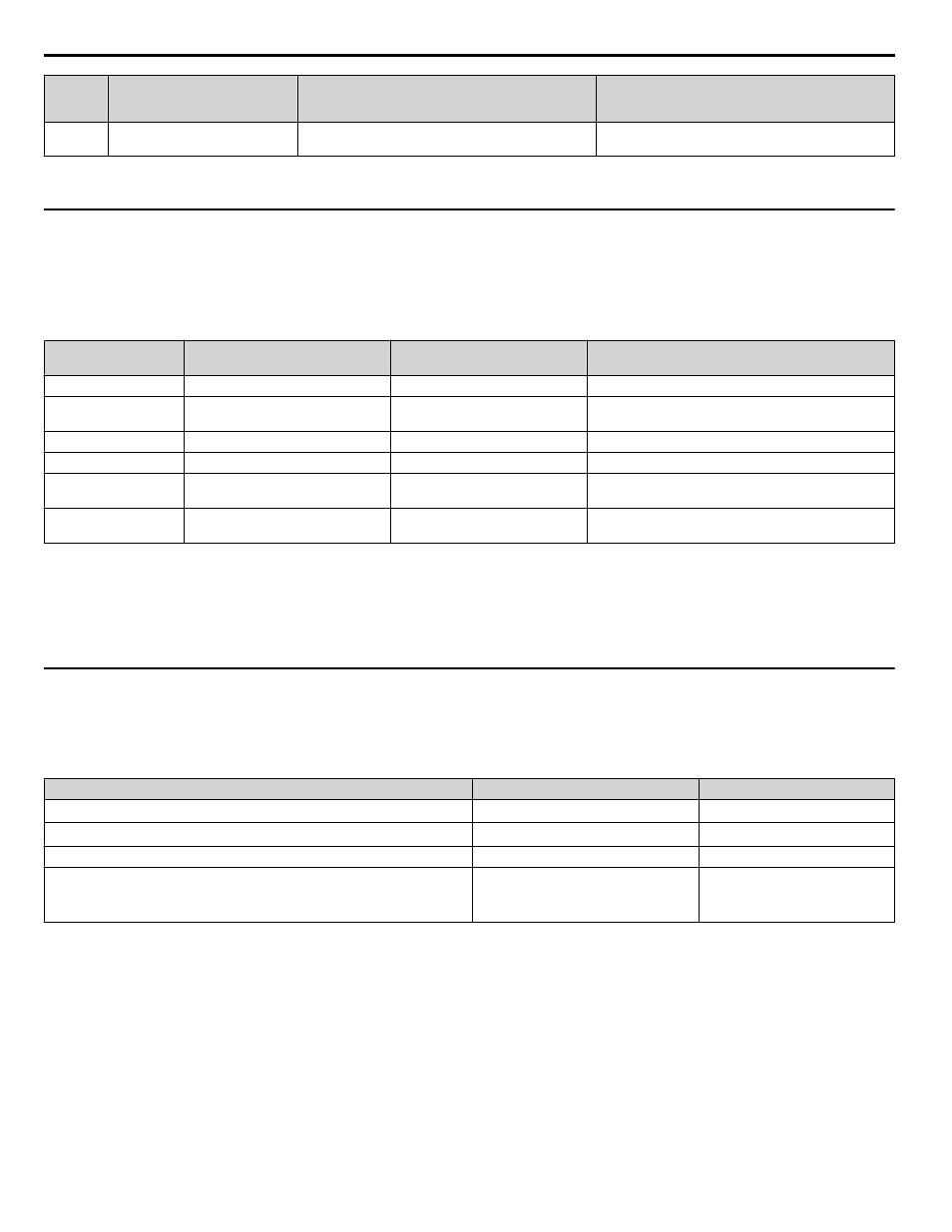
Error
Code
(Hex)
Description
Cause
Possible Solution
20
Invalid parameter
Attempted to change to a data value outside the setting
range.
Specify a data value within the setting range.
Note:
Refer to the MEMOBUS/Modbus Data Table in the MEMOBUS/Modbus Communications chapter of the drive manual for a list of monitor
data using the MEMOBUS/Modbus message area.
u
Option Error Codes
n
Option Fault Monitors U6-98 and U6-99
The option can declare error/warning conditions via drive monitor parameters on the drive digital operator as shown in
.
Table 15 Option Fault Monitor Descriptions
Fault Condition
Fault Declared
Status Value
(U6-98/U6-99)
Description
No Fault
n/a
0
No faults
Force Fault
EF0
3
Network sent a message to force this node to the fault
state.
Network Link Down
BUS ERROR
1100
No network link to option.
Connection Timeout
BUS ERROR
1101
The node timer (Requested Packet Interval) timed out.
Duplicate IP Address
BUS ERROR
1102
This node and at least one other node have the same IP
Address.
Default MAC Address
None
1103
Factory default MAC Address programmed into the
option. Return for reprogramming.
Two drive monitor parameters, U6-98 and U6-99 assist the user in network troubleshooting.
• U6-98 displays the first declared fault since the last power cycle. U6-98 is only cleared upon drive power-up.
• U6-99 displays the present option status. U6-99 is cleared upon a network-issued fault reset and upon power-up.
If another fault occurs while the original fault is still active, parameter U6-98 retains the original fault value and U6-99 stores
the new fault status value.
u
Option Compatibility
A limited number of options may be simultaneously connected to the drive depending on the type of option.
below lists the number of options that can be connected to the drive and the drive ports for connecting those options.
Table 16 Option Installation
Option
Port/Connector
Number of Options Possible
PG-B3, PG-X3
CN5-C
2
<1>
PG-F3
<2> <3>
, PG-RT3
<2> <3>
CN5-C
1
AO-A3, DO-A3
CN5-A, B, C
1
SI-B3
<3>
, SI-C3, SI-EN3
<3>
, SI-EN3D, SI-EM3
<3>
, SI-EP3
<3>
, SI-
ES3
<3>
, SI-ET3
<3>
, SI-N3, SI-P3, SI-S3, SI-T3, SI-W3
<3>
, AI-A3
<4>
,
DI-A3
<4>
CN5-A
1
<1> When connecting two PG option cards, use both CN5-B and CN5-C. When connecting only one PG option card, use the CN5-C connector.
<2> Not available for the application with Motor 2 Selection.
<3> Not available with models 4A0930 and 4A1200.
<4> When using AI-A3 and DI-A3 as monitors, the card can be connected to any of CN5-A, CN5-B or CN5-C. The input status of AI-A3 can then be
viewed using U1-21, U1-22, and U1-23, and the input status of DI-A3 can then be viewed using U1-17.
13 Troubleshooting
62
YASKAWA SIEP YAICOM 16A 1000-Series Option Dual-Port EtherNet/IP SI-EN3D Technical Manual