Yaskawa SI-EN3D User Manual
Page 26
Name
Description
Multi-Function
Photocoupler 1
Terminal P1
0: P1 OFF
1: P1 ON
This function is enabled only when H2-02 is set to F.
Multi-Function
Photocoupler 2
Terminal P2
0: P2 OFF
1: P2 ON
This function is enabled only when H2-03 is set to F.
Speed Reference
Speed Command
Sets drive speed reference.
Unit depends on o1-03.
Unit is not affected by Speed Scale SS.
Torque Reference/Torque
Limit
Torque Reference/Torque Limit
Sets the Torque Reference/Torque Limit in units of 0.1%.
Sets the Torque Reference when using Torque Control (d5-01 = 1).
Sets the Torque Limit when using Speed Control (d5-01 = 0).
The Torque Reference and Torque Limit are disabled with F6-06 = 0.
Torque Compensation
Sets the amount of Torque Compensation Sets in units of 0.1%.
Analog Output 1
MEMOBUS/Modbus (0x0007)
Analog Output 2
MEMOBUS/Modbus (0x0008)
Digital Outputs
MEMOBUS/Modbus (0x0009)
u
High Speed/Torque Control Output (Vendor Specific Yaskawa Electric (YE) Assy) - 116
(0x74)
This assembly is dynamic and can be configured as to what parameters are used. The first 20 Bytes (0-19) are fixed and the
next 20 Bytes can be configured using parameters F7-23 to F7-32. If an error occurs while trying to write to the dynamic
parameters, the appropriate error bit in Assembly 166 will be set. If more information is needed as to the nature of the error,
the extended error status can be read explicitly through Class 4, Instance 0xA6, Attribute 0x64. This will return 20 Bytes with
each dynamic parameter in Assembly 116 having a Byte dedicated to its extended error status.
for more information.
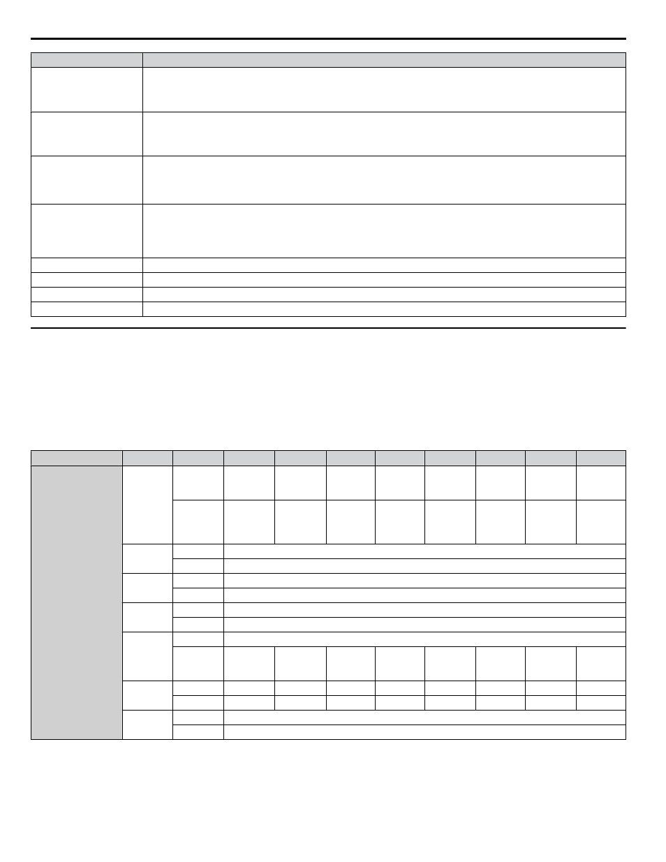
Output Instance
Word
Byte
Bit 7
Bit 6
Bit 5
Bit 4
Bit 3
Bit 2
Bit 1
Bit 0
116
0
0
Multi-
Function
Input 8
Multi-
Function
Input 7
Multi-
Function
Input 6
Multi-
Function
Input 5
Multi-
Function
Input 4
Multi-
Function
Input 3
Run Rev
Run Fwd
1
Multi-
Function
Photo-
coupler 2
Multi-
Function
Photo-
coupler 1
Multi-
Function
Digital
Output
–
–
–
Fault Reset
External
Fault
1
2
Speed Reference (Low Byte)
3
Speed Reference (High Byte)
2
4
Torque Reference/Torque Limit (Low Byte)
5
Torque Reference/Torque Limit (High Byte)
3
6
Torque Compensation (Low Byte)
7
Torque Compensation (High Byte)
4
8
Reserved
9
–
–
–
–
Multi-
Function
Input 12
Multi-
Function
Input 11
Multi-
Function
Input 10
Multi-
Function
Input 9
5
10
–
–
–
–
–
–
NetCtrl
NetRef
11
–
–
–
–
–
–
–
–
6
12
Analog Output 1 (Low Byte)
13
Analog Output 1 (High Byte)
8 Output Assemblies (Drive Consumes)
26
YASKAWA SIEP YAICOM 16A 1000-Series Option Dual-Port EtherNet/IP SI-EN3D Technical Manual