9 cable connection – SMA TCS 500SC-JP User Manual
Page 33
SMA Solar Technology AG
7 Electrical Connection
Installation Manual
TCS-JP-IA-en-10
33
7.9 Cable Connection
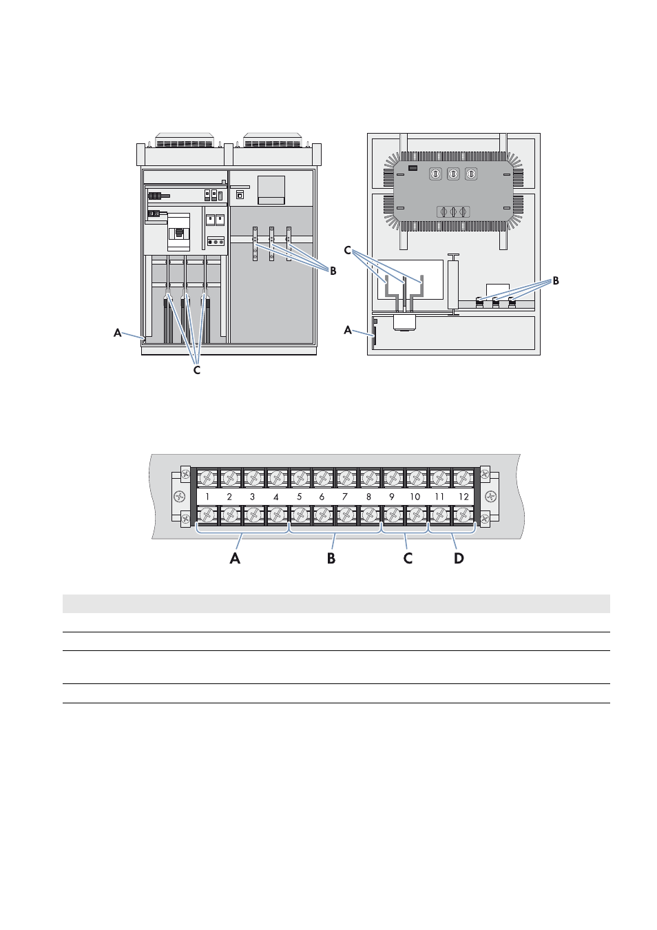
7.9.1 Connection Areas of the Transformer Compact Station
Figure 20: Overview of the connection areas in the Transformer Compact Station (front and top view)
Detailed View of the Connecting Terminal Plate for Inverter Supply, Fan Supply and Transformer
Protection Unit
Figure 21: Detailed view of the connecting terminal plate for inverter supply, fan supply and transformer protection unit
Position Designation
Explanation
A
Station supply
Clamping area for the voltage supply to the station
B
Inverter supply
Clamping area for the voltage supply to the inverter
C
Signal terminal for the transformer
protection unit
Clamping area for the signal cables of the transformer protection unit
D
Reserve
Reserve