7 technical data of the communication interface – SMA STP 60-US-10 Installation User Manual
Page 51
SMA Solar Technology AG
5 Technical Data
Installation Guide
STP60-10-IA-xx-10
51
5.7 Technical Data of the
Communication Interface
Table 5.9 Technical data of the communication interface
1)
For outdoor use, ensure that an appropriate cable is used. If the
cable is very stiff, an intermediate terminal should be used in
order to change from a stiff to a more flexible cable before
entering the inverter. For some cables it might be sufficient to
remove the hard outer mantle of the part of the cable inside
the inverter enclosure. This is to protect the PCB-mounted
RJ-45 Ethernet ports from excessive strain, which could lead
to damage or connection issues.
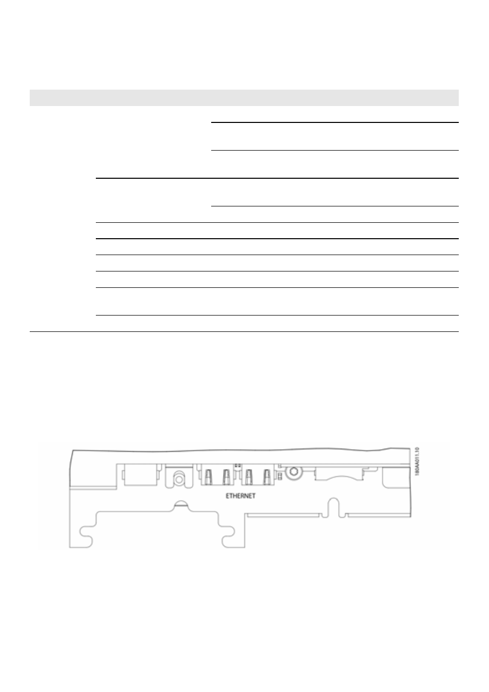
Figure 5.3 Auxiliary interfaces (cutout of Communication PCB with
RJ-45 Ethernet ports)
Interface
Parameter
Parameter details
Specification
Ethernet
Cables
Cable sheath diameter ( ⌀ )
2 x 5 to7 mm
Cable type
STP cable (Shielded Twisted Pair,
CAT 5e or SFTP CAT 5e)
1)
Cable characteristic
impedance
100 Ω to 120 Ω
RJ-45 connector: 2 pcs. RJ45
for Ethernet
Wire size
24 to 26 AWG (depending on
design of the RJ-45 plug)
Cable shield termination
Via RJ-45 plug
Galvanic interface insulation
Yes, 500 Vrms
Direct contact protection
Double/reinforced insulation
Yes
Short-circuit protection
Yes
Communication
Network topology
Star and daisy chain
Cables
Maximum cable length
between inverters
100 m (328 ft)
Max. number of inverters
Per SMA Inverter Manager
42