10 closure, 3 initial setup and start, 1 user interface – SMA STP 60-US-10 Installation User Manual
Page 29: 1 operating modes
SMA Solar Technology AG
3 Initial Setup and Start
Installation Guide
STP60-10-IA-xx-10
29
Protection class of PV modules
The inverter must only be operated with PV modules of
protection class II, compliant with IEC 61730, application
class A.
Only connect PV modules to the inverter. Other energy
sources are not allowed.
2.10 Closure
1. Close the cover of the inverter installation area. Fasten
the three front screws. See Section 5.5, page 50.
2. Turn on AC power.
3 Initial Setup and Start
3.1 User Interface
The user interface comprises:
• Local display, for all inverter variants. The local display
shows status information of the inverter. It is not
possible to configure or set up the STP 60 inverter via
the display. The "#" in the display explains the
operation modes.
• Local commissioning and service tool (LCS tool). The
LCS tool enables configuration of one or multiple
STP 60 inverters.
3.1.1 Operating Modes
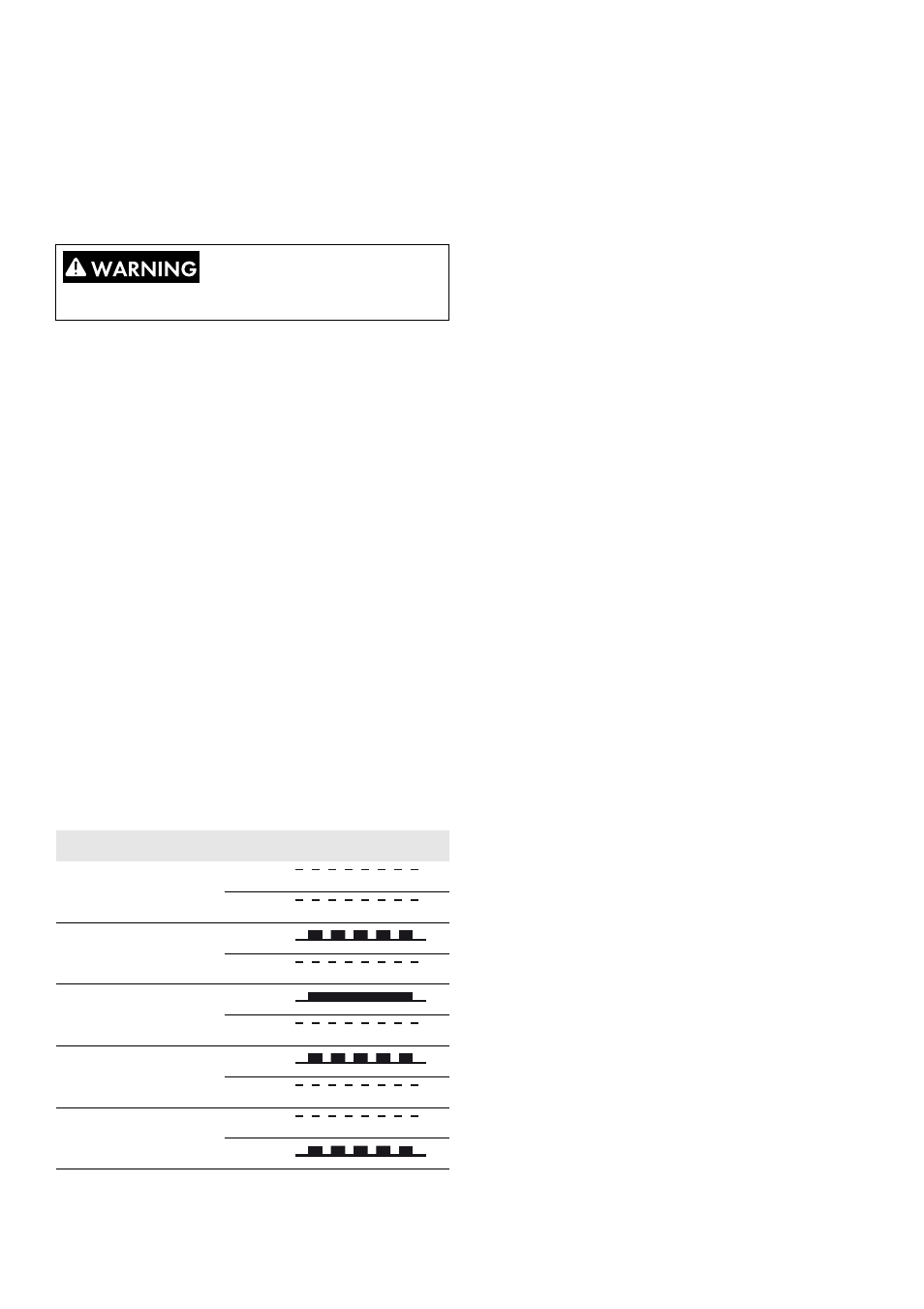
The inverter has five operation modes, indicated by LEDs.
Table 3.1 Operating modes
Off grid (standby) (LEDs off)
#0-51
When no power has been delivered to the utility grid for
more than ten minutes, the inverter disconnects from the grid
and shuts down. User and communication interfaces remain
powered for communication purposes.
Connecting (green LED flashing)
#52 to 53
The inverter starts up when the PV input voltage reaches the
minimum DC feed-in voltage. The inverter performs a series
of internal self-tests, including measurement of the resistance
between the PV arrays and ground. Meanwhile, it also
monitors the grid parameters. When the grid parameters
have been within the specifications for the required amount
of time (depends on grid code), the inverter starts feeding
into the utility grid.
On grid (green LED on)
#60
The inverter is connected to the utility grid and feeds into the
utility grid. The inverter disconnects when:
• it detects abnormal grid conditions (dependent on grid
code),
• an internal event occurs, or
• PV power is insufficient (no power is supplied to the
grid for ten minutes).
The inverter then enters connecting mode or off-grid mode.
Internal inverter event (green LED flashing)
#54
The inverter is waiting for an internal condition to be within
thresholds (for example when the temperature is too high)
before it re-connects to the utility grid.
Fail safe (red LED flashing)
#70
If the inverter detects an error in its circuits during the self-test
(in connecting mode) or during operation, the inverter goes
into fail safe mode, disconnecting from the grid. The inverter
will remain in "fail safe" mode until power has been absent
for a minimum of ten minutes, or the inverter has been shut
down completely (AC+PV).
PV modules generate a voltage when exposed to light.
Status
LEDs
LEDs
Off grid
Green
Red
Connecting
Green
Red
On grid
Green
Red
Internal inverter event Green
Red
Fail safe
Green
Red