5 torque specifications, 6 specifications for grid protection – SMA STP 60-US-10 Installation User Manual
Page 50
5 Technical Data
SMA Solar Technology AG
50
STP60-10-IA-xx-10
Installation Guide
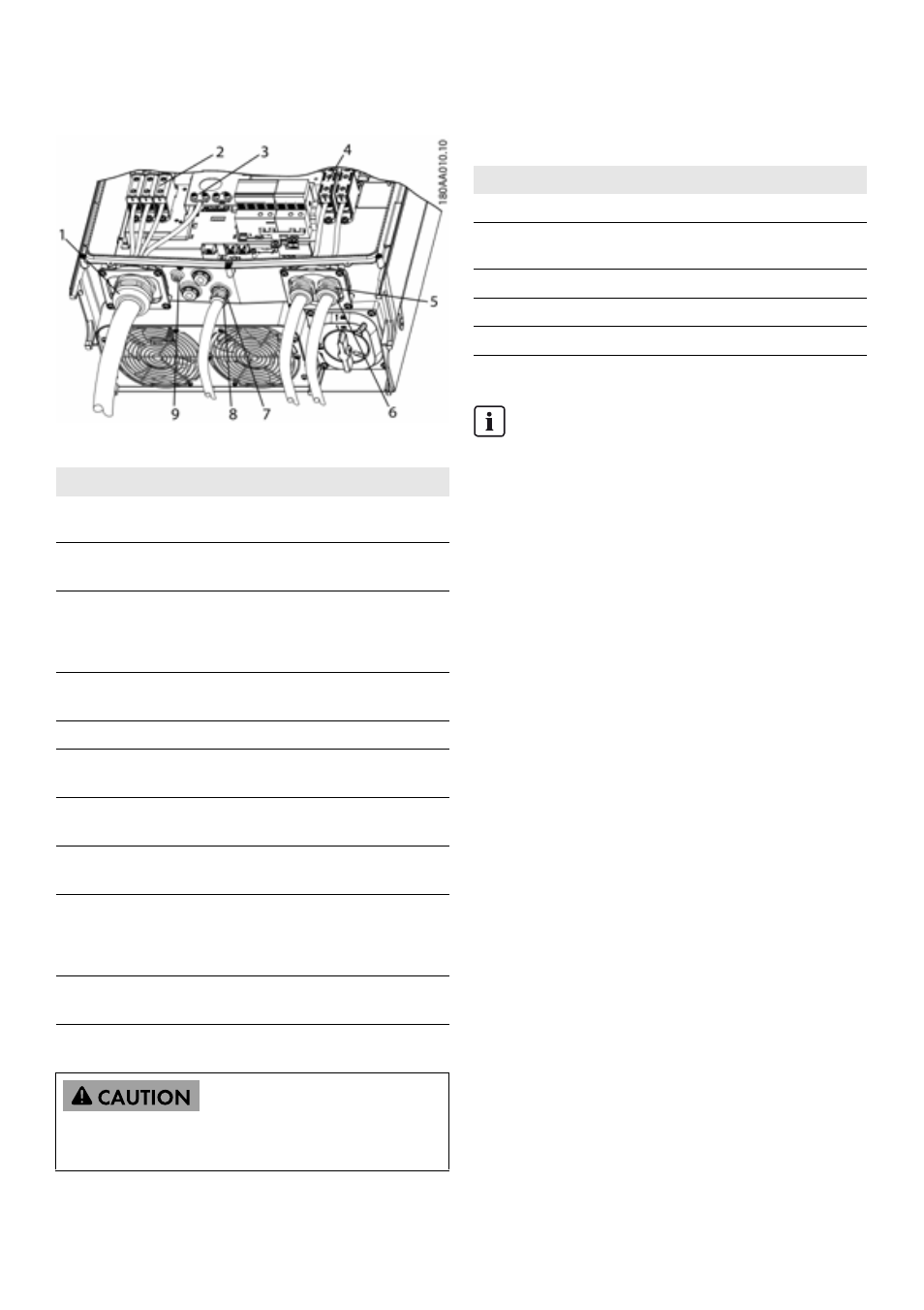
5.5 Torque Specifications
Figure 5.2 Overview of Inverter with Torque Indications
Table 5.7: Torques
5.6 Specifications for Grid
Protection
Table 5.8: Specifications for grid protection
Parameter
Tools
Torque
1
M63 cable gland
Wrench 65/68
mm
6 Nm (53 in-lbf)
2
Terminals on AC
terminal block
TX 30
14 Nm
(124 in-lbf)
3
Primary PE
(secondary PE to
the immediate
right)
TX 30
3.9 Nm
(35 in-lbf)
4
Terminals on DC
TX 30
14 Nm
(124 in-lbf)
5
M32 cable gland
Wrench, 36 mm
6 Nm (53 in-lbf)
6
Swivel nut for M32
cable gland
Wrench, 36 mm
1.8 Nm
(16 in-lbf)
7
M25 cable gland
Wrench 33 mm
10 Nm
(89 in-lbf)
8
Swivel nut for M25
cable gland
Wrench 33 mm
1.8 Nm
(16 in-lbf)
9
M6 equipment
grounding
(equipotential
bonding terminal)
TX 20
3.9 Nm
(35 in-lbf)
Front screw (not
shown)
TX 30
1.5 Nm
(13 in-lbf)
If the blind plugs are removed (see (7) in figure 5.2 ), use
the following fittings: 3, 3S, 4, 4X, 6, 6P.
Parameter
Specification
Maximum inverter current, I
ACmax
87 A
Recommended blow fuse type gL/gG (IEC
60269-1)
100 to125 A
Recommended blow fuse Class T (UL/USA)
125 A
Recommended circuit breaker type B or C
125 A
Maximum fuse size
125 A
INFORMATION
Observe local regulations.