6 grid connection, Section 2.6 – SMA STP 60-US-10 Installation User Manual
Page 25
SMA Solar Technology AG
2 Installation
Installation Guide
STP60-10-IA-xx-10
25
2.6 Grid Connection
IMI Detection
The inverter has built-in IMI/RCMU (Insulation Monitoring
Interrupter / Residual Current Monitoring Unit) according to
the UL 1741 for non-isolated EPS interactive PV inverters. It
acts on continuous ground fault current and a sudden
change in the ground fault current. This functionality is
activated during normal operation.
Insulation Resistance Detection
The inverter has a built-in insulation resistance detection /
ISO circuit, which is certified according to the UL 1741 for
non-isolated EPS interactive PV inverters. The insulation
resistance detector performs a measurement of the
connected PV system resistance to ground before the
inverter connects to the grid. If the resistance is below the
grid code set value, the inverter will wait and re-measure the
resistance after a short while. When the resistance is above
the grid code set value, the inverter performs a self-test and
connects to the grid.
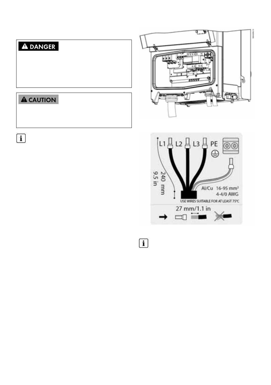
Figure 2.16 Installation area
Figure 2.17 AC cable wire strip
These instructions for utility grid connection are for
qualified personnel only. To reduce the risk of electric
shock, do not perform any maintenance work other than
that specified in the user manual unless you are qualified
to do so.
For fuse and RCD information, refer to Section 5,
page 45. AC fuse rating must not exceed the ampacity of
the conductors used.
INFORMATION
All electrical installations in the U.S. and Canada
must be made in accordance with the local standards
and National Electrical Code
®
ANSI/NFPA70 or
the Canadian Electrical Code
®
CSA C22.1.
• Before connecting the inverter to the utility grid,
contact your local grid operator. The electrical
connection of the inverter must be carried out by
qualified persons only.
• Ensure that no cables used for electrical
connection are damaged.
INFORMATION
For AC connection, cables with multi-strand,
fine-strand or extra fine-strand conductors can be
used (see figure 2.18).
When using fine-strand or extra fine-strand
conductors, bootlace ferrules must be used for the
connection.