8 ethernet connections, 9 pv connection, 1 external pv array junction boxes – SMA STP 60-US-10 Installation User Manual
Page 27: 8 ethernet connections 2.9 pv connection, Section 2.9
SMA Solar Technology AG
2 Installation
Installation Guide
STP60-10-IA-xx-10
27
Table 2.1 Suitable conductor sizes
1)
Always observe the ampacity of cables used.
2.8 Ethernet Connections
For outdoor use, ensure that an appropriate cable is used.
If the cable is very stiff, an intermediate terminal should be
used in order to change from a stiff to a more flexible cable
before entering the inverter. For some cables it might be
sufficient to remove the hard outer mantle of the part of the
cable inside the inverter enclosure. This is to protect the
PCB-mounted RJ-45 Ethernet ports from excessive strain,
which could lead to damage or connection issues.
Procedure:
1. Do not remove the RJ-45 connector on the Ethernet
cable.
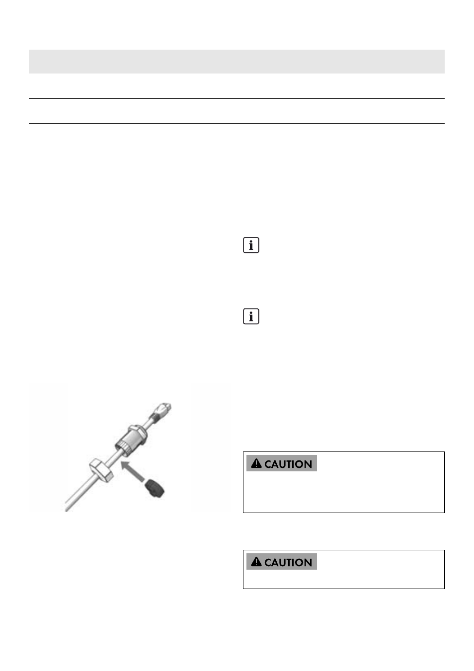
2. Run the cables through the base of the inverter via
cable glands. See figure 2.22.
3. Cut slice in rubber grommet. Place the grommet in the
gland to ensure proper seal.
4. Plug into the Ethernet connector.
Figure 2.22 Run cables through cable glands
2.9 PV Connection
2.9.1 External PV Array Junction
Boxes
PV strings must be connected to the DC input via an external
PV array junction box. The PV array junction box connects
the PV strings of the PV array and protects the individual
strings against overcurrent.
Use a suitable voltage detector that can measure up to
1,000 V DC. Verify the polarity and maximum voltage of
the PV arrays by measuring the PV open-circuit voltage. The
inverter is protected against reversed polarity and will not
generate power until the polarity is correct.
The combined output from the DC combiner must be
connected to the DC input of the STP 60 inverter.
The DC power can be disconnected with the
inverter-integrated DC load-break switch.
Terminal
Range
1)
Max. conductor
temperature rating
Conductor
material
Cable sheath diameter with supplied
cable gland
AC+PE
16 to 95 mm²
6 to 4/0 AWG
90ºC
Al/Cu
37 to 44 mm
PV
16 to 95 mm²
6 to 4/0 AWG
90ºC
Al/Cu
14 to 21 mm
INFORMATION
The same number and type of modules must be
connected to all PV strings connected to the PV array
junction box. In addition, all connected modules must
have the same orientation.
INFORMATION
Observe correct fuse rating. Consult module
manufacturers' manuals for information on correct
string fuse rating.
PV array is floating, with both the (+) and (-) conductors
connected to the inverters' PV inputs. Neither conductor is
connected to ground.
Do NOT connect PV to ground!