Detailed explanation of aspb cabling, Audio clock cabling, Audio clock groups and reference selection – Grass Valley Profile Family Audio Signal Processing Board User Manual
Page 57: Connecting audio clock and sharcnet cables
Connecting Audio Clock and Sharcnet Cables
ASPB Installation
57
Detailed Explanation Of ASPB Cabling
If you are following one of the cabling examples or the cabling instructions, this
section is for reference only. Read this information if you have questions about the
ASPB cabling.
Audio Clock Cabling
When the Profile system records, audio sampling must be referenced to the video
signal, otherwise audio artifacts will occur. The ASPB hardware and Profile
software allows the you to select the appropriate audio sample reference for
recording as follows:
• When recording synchronous video feeds, use “system clock” derived from
house reference and supplied to the ASPB through its motherboard
connector.
• When recording non-synchronous video feeds, use the reference signal
supplied by the video input card over an Audio Clock coaxial cable
connected to the ASPB.
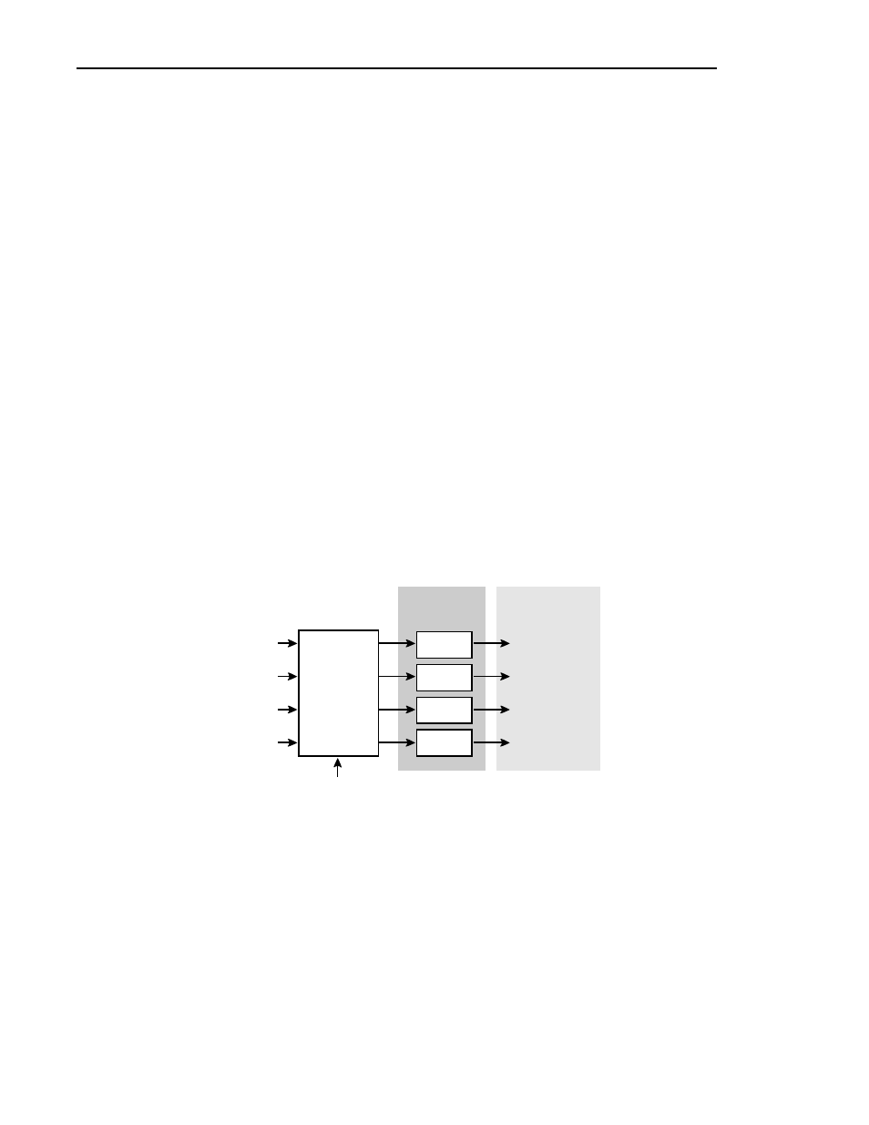
Each ASPB has four audio clock input connectors for attaching an audio clock
reference. These connectors are attached by coaxial cable to the video input
boards. The cables carry a 27MHz reference signal derived from the video input
to the ASPB. This signal is used as a reference for the audio phase lock loops.
(See Figure 19.)
Figure 19. Audio clock groups and reference selection
0047-14
Audio Clock1
Audio
Sample PLLs
Audio
Sample Clocks
Group1
Group1 Clock
(Channels 1-4)
Audio Clock2
Group2
Group2 Clock
(Channels 5-8)
Audio Clock3
Group3
Group3 Clock
(Channels 9-12)
Audio Clock4
System Clock
(from Genlock bd. through
the Motherboard connector)
Group4
Group4 Clock
(Channels 13-16 )
Reference
Select
Crosspoint