Audio clock cabling example in the pdr 100, Figure 15, Figure 15) – Grass Valley Profile Family Audio Signal Processing Board User Manual
Page 51: Nd figure 15, Connecting audio clock and sharcnet cables
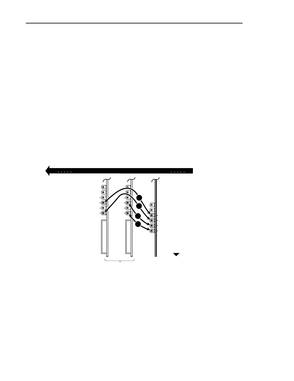
Connecting Audio Clock and Sharcnet Cables
ASPB Installation
51
4. To connect the fourth audio clock cable to the ASPB:
a. Connect one end of an audio clock cable to the ASPB Audio Clock4.
b. Connect the other end of the cable to Channel B of the same video input
board to which the previous clock cable was attached
(
Í in example Figure 15) or to Channel A of the video input board in the
next higher numbered board slot (
Í in example Figure 13).
NOTE: If you have more than four video inputs, it is important that you refer
to“Detailed Explanation Of ASPB Cabling” on page 59.
5. After installing the ASPB audio clock cables do one of the following:
a. If you have Serial Digital I/O boards with Sharcnet connectors go to
“Connecting Sharcnet Cables To The Serial Digital I/O Boards” on
page 53.
b. If you have no Serial Digital I/O boards with Sharcnet connectors go to
“Reassembling the Profile Chassis” on page 63.
Figure 15. Audio Clock cabling example in the PDR100
0047-12
1
2
3
4
ASPB
Video Boards
J1
J17
A
A
B
B
A
A
B
B
1
2
3
4
Rear of Unit