Audio clock cabling example for aspb2, Connecting audio clock and sharcnet cables – Grass Valley Profile Family Audio Signal Processing Board User Manual
Page 49
Connecting Audio Clock and Sharcnet Cables
ASPB Installation
49
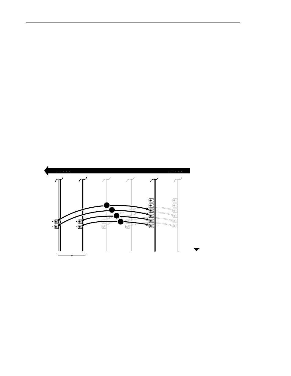
6. To connect the remaining ASPB2 audio clock cables:
a. Proceeding with ASPB2 Audio Clock2, repeat step 5 until all remaining
video input references are connected or until all four ASPB2 audio clock
connectors are used (
Ë, Ì, Í in example Figure 14).
NOTE: If you have more than eight video inputs, it is important that you refer
to “Detailed Explanation Of ASPB Cabling” on page 59.
b. When you are finished, compare your ASPB2 cabling with the example
in Figure 14.
7. After installing the ASPB1 and ASPB2 clock cables do one of the following:
a. If you have Serial Digital I/O boards with Sharcnet connectors go to
“Connecting Sharcnet Cables To The Serial Digital I/O Boards” on
page 53.
b. If you have no Serial Digital I/O boards with Sharcnet connectors go to
“Connecting Sharcnet Cables Between Two ASPBs” on page 57.
Figure 14. Audio Clock cabling example for ASPB2
0047-11
A
B
A
B
1
2
3
4
ASPB1
ASPB2
1
2
3
4
J1
J17
Video Boards
Rear of Unit