Indicator leds on power supplies, Indicator leds on control cards, Indicator leds on input and output cards – Grass Valley NV5128 v.2.5 User Manual
Page 87: Test points, Maintenance
NV5128 Multi-Format Router • User’s Guide
77
6. Maintenance
Indicator LEDs
Indicator LEDs on Power Supplies
The five green LEDs on the front of the power supply modules indicate presence of the five +48
VDC outputs of the five branch circuits. All five LEDs should be lit at all times when AC power is
present. If any LED is off, either the power supply has failed or the branch circuit is shorted.
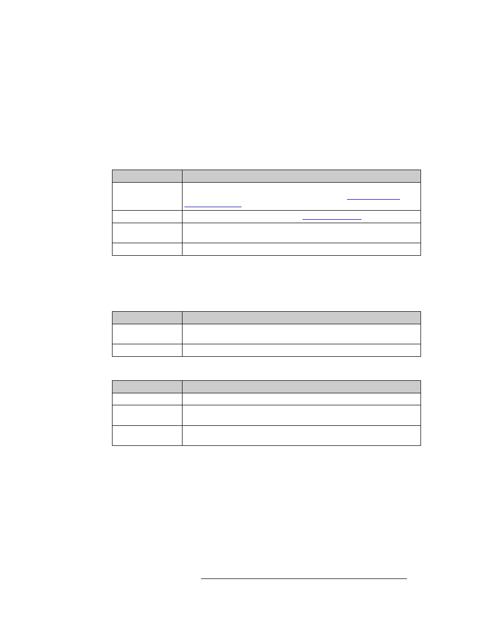
Indicator LEDs on Control Cards
The LEDs on the front of the control cards can be monitored to determine whether the card is oper-
ating normally. The meanings of the LED indicators are as follows:
Indicator LEDs on Input and Output Cards
The LEDs on the front of the input and output cards can be monitored to determine whether the
cards are operating normally. The LEDs indicate the following:
Three additional LEDs situated further back on the output card indicate the following:
Test Points
All active cards, except the control cards, feature power supply test points located in the same pat-
tern along the lower portion of the front edge. This simplifies verification of power supply status.
Test points are provided only for voltages actually present on the module.
The matrix controller also provides front card edge mounted test points. These are in a slightly dif-
ferent pattern than the matrix modules, but are clearly labeled for function.
LED Indicator
Indicator Function
Red (alarm)
Indicates a problem or fault. Check the external reference signals; if this does not
resolve the problem, call Miranda Technical Support (see
Red (low battery)
Indicates the battery needs replacing. See
Amber (active)
Indicates the card is the active control card. On the reserve control card, this LED
should be OFF.
Green (health)
Normally ON. Indicates the card is operating normally.
LED Indicator
Indicator Function
Red (alarm)
Normally OFF. If it is lit, it indicates a problem; replace the card or call Miranda
Technical Support.
GREEN (Power)
Normally ON. Indicates the card is operating normally and receiving power.
LED Indicator
Indicator Function
Amber (health)
Normally ON. Indicates software has loaded and the card is operating normally.
Green (good
communication)
Normally ON. Indicates good communication with the control card.
Red (bad
communication)
Normally OFF. If lit, indicates that communication is not working properly with the
control card; the communication is “bad.”