Installing classic swb backplanes, Installation – Grass Valley NV5128 v.2.5 User Manual
Page 51
NV5128 Multi-Format Router • User’s Guide
41
3. Installation
Installing Backplanes
Each backplane must have a corresponding input card or output card installed in the associated slot.
For example, if a backplane for receiving SD signals is installed, a corresponding SD input card
must be installed in the associated card slot. Typically, for each backplane installed to receive a spe-
cific type of signal, a corresponding backplane is installed that distributes the same type of signal.
For more information, see
Installing Classic SWB Backplanes
Classic SWB backplanes contain 16 BNC connectors and must be installed in specific slots. Install
these backplanes first. Before installing Classic SWB backplanes, review
When installing Classic SWB backplanes in the frame, the silk-screened slot designations on the
rear of the frame are incorrect. To remedy this, a thin plate with the correct I/O designations is
included with the Classic SWB backplanes. This plate should be installed on top of the existing leg-
ends.
Each Classic SWB card set requires two backplanes: One is a 16-input active backplane; it includes
automatic cable equalization circuits for the 16 inputs. The other is an output backplane with active
line drivers for the 16 outputs. One Classic SWB card set supports 16 inputs x 16 outputs.
How to install a Classic SWB backplane
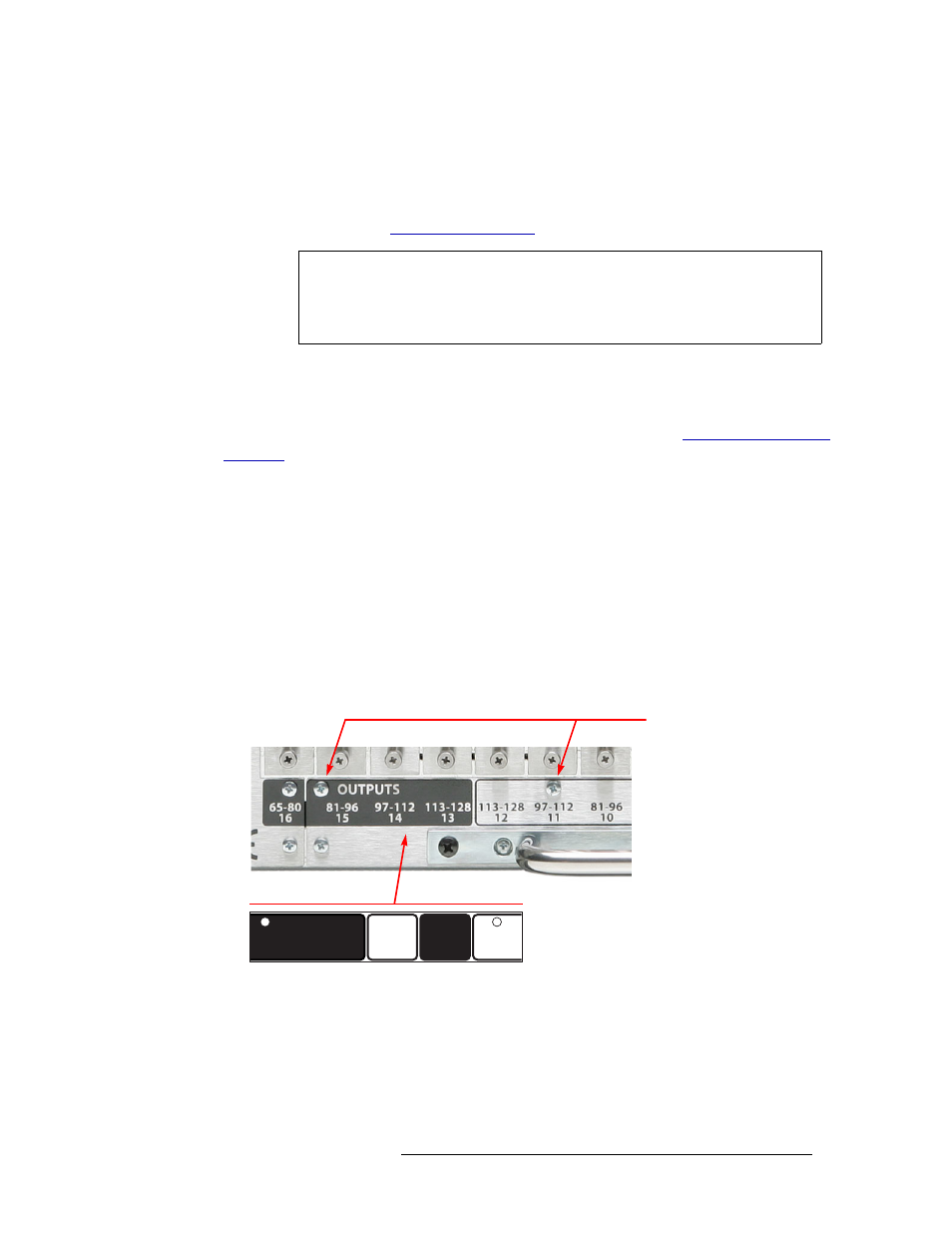
1 Facing the rear of the router, locate the legend plate, as shown in Figure 3-4.
2 Remove the two screws, as shown Figure 3-4.
Figure 3-4. Classic SWB Legend Plate (Rear View)
3 Place the new Classic SWB legend plate over the existing plate, aligning the two screw holes.
4 Reinstall the screws removed in Step 2.
5 Locate the Classic SWB backplanes for inputs (EM0396) and outputs (EM0424).
6 Important: If any Classic SWB card sets are currently installed, unseat the card set before
installing the associated backplanes.
Caution
Although different backplanes may appear to be identical (e.g., contain the same
type of connectors), some have active components while others do not. Always
verify that the correct backplane is being for the associated front-loaded active
input card or output card.
SWB
97-112
11
OUTPUTS
SWB
97-112
11
INPUTS
SWB
113-128
13
OUTPUTS
SWB
97-112
12
SWB
113-128
14
OUTPUTS
81-96
15
Remove these two screws