Time code signals, Input card, Introduction – Grass Valley NV5128 v.2.5 User Manual
Page 42
32
Rev 2.5 • 24 Sep 09
2. Introduction
Active Cards
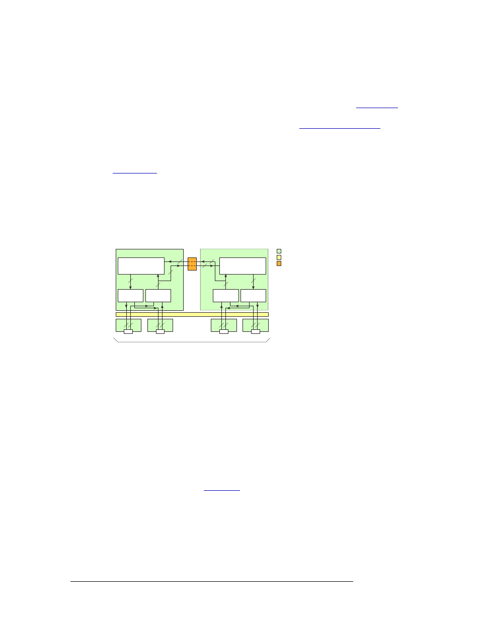
The Machine Control card set differs from other modules in that it is bi-directional. A Machine
Control card set is neither an “input” nor an “output” card; it carries signals in both directions. The
architecture of the Machine Control card set is similar to the Classic SWB card set: the port card set
occupies two slots and uses two backplanes supporting up to 32 signals. (See
page 28.) Two card sets can be linked together, cross-coupling the inputs from each card set to the
other card set, creating 64 ports. For more information, see
The port card set has one jumper used to configure the card set to function as a standalone 32-port
card set regardless of where it is installed in the frame. This means that two 32 inputs x 32 inputs
matrixes can be installed instead of one 64 inputs x 64 inputs matrix. For more information, see
Incoming and outgoing signals are buffered by differential transmitters and receivers on the card
set. When two Machine Control card sets are connected, signals are sent directly to the 64 inputs x
32 outputs crosspoint array on each card set for switching (creating a 64 inputs x 64 outputs switch-
ing matrix) without going through the motherboard.
Figure 2-26 shows the signal flow path through a pair of Machine Control card sets.
Figure 2-26. Machine Control Signal Flow (64-Port Configuration)
Time Code Signals
The NV5128 supports SMPTE time code signals. A time code is a sequence of numeric codes gen-
erated at regular intervals by a timing system. Time codes are usually used to synchronize a variety
of signals to a specific start and end time, without regard to any other timing device. For example, a
production plant may use a time code signal to which all signals distributed within the plant are
synchronized. This ensures synchronization of signals to a single “master” clock instead of individ-
ual equipment clocks.
Input Card
The time code input card (EM0408) receives 16 time code signals through 16 Phoenix connectors
housed on a backplane. (See
on page 13.) 16 differential input receivers accept time
code input signals from the input backplane. The receivers send the single-ended outputs to Low
Voltage Differential Signal (LVDS) buffers and then to the motherboard. The signal format on the
motherboard is differential.
32
32
Transmitters
(×32)
EM0482 Port Module
32
16
64×32 Crosspoint Array
and Port Control Logic
Receivers
(×32)
16
32
16
Modules
Motherboard
Transmitters
(×32)
Special Motherboard Traces
EM0482 Port Module
32
16
116
RJ-45 Ports
64×32 Crosspoint Array
and Port Control Logic
Receivers
(×32)
32
16
16
16
32
EM0383
Backplanes
1732
3348
4964
16
32
Slots 12 and 13
Slots 14 and 15