Video signals, Installation – Grass Valley NV5128 v.2.5 User Manual
Page 64
54
Rev 2.5 • 24 Sep 09
3. Installation
Making Signal Connections
Connect the signal or “hot” wire from the single ended source to the balanced input “+” connec-
tion. Connect the common or “shield” wire from the single ended source to the balanced input
“–” connection. Bridge the balanced input ground pin to the “–” pin, or single ended shield.
The following lists the signal managed by each pin:
3 Connect the other end of the cable for each input to the source of the signal.
4 Locate the analog output connections on the rear of the router, as shown in Figure 3-8 on page
5 For each output, connect using a DB25 connector and cable, wiring the connectors as described
in Step 2.
6 Connect the other end of the cable to the signal destination.
7 Make other signal connections, as needed.
Video Signals
The NV5128 can support SD, SWB and analog video signals. Each requires a unique backplane
and signal connections. SD, SWB and analog video signals are received and distributed through 16
BNC connectors labeled ‘1’, ‘2’ and so on up to ‘16’. Connections are housed on a backplane
installed in the back plate. The labels correspond to the signal number assigned to the signal pass-
ing through that connector. (See
on page 13.) However, the backplanes for incoming
SD signals and for incoming and outgoing SWB signals contain active connections; the backplane
for analog video signals contains passive connections. Do not intermix backplanes! SD and SWB
backplanes cannot be used for analog video signals, SD backplanes for SWB signals, and so on.
3 - Right
6
BLUE
4
17
5
4 - Left
7
VIOLET
15
3
16
4 - Right
8
GRAY
1
14
2
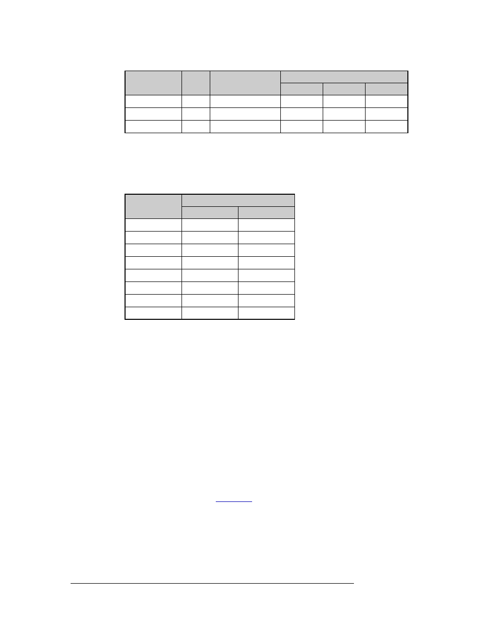
*Note: Pin 13 is not used.
Channel
DB25 Connector Pin Number
Signal
Common
1 - Left
24
12 & 25
1 - Right
10
11 & 23
2 - Left
21
9 & 22
2 - Right
7
8 & 20
3 - Left
18
6 & 19
3 - Right
4
5 & 17
4 - Left
15
3 & 16
4 - Right
1
2 & 14
*Note: Pin 13 is not used.
Channel
Pair
Jacket Color
DB25 Connector Pin Number
Red (+)
Black (–)
GND