Installing backplanes, Installation – Grass Valley NV5128 v.2.5 User Manual
Page 50
40
Rev 2.5 • 24 Sep 09
3. Installation
Installing Backplanes
6 Connect the other end of the power supply cable to a source of AC power source (90-130/180-
230
VAC, 50/60
Hz).
7 Install the PS6000 power supply modules as follows:
a Facing the front of the NV5128, install the primary PS6000 power supply module in the
primary power supply slot, as shown in Figure 3-1 on page 39.
b (Optional) Facing the front of the NV5128, install the redundant PS6000 power supply
module in the secondary power supply slot, as shown in Figure 3-1 on page 39.
8 Facing the rear of the NV5128, connect the ground lug to ground using a copper wire from 14
to 6 AWG. The ground lug is located in the lower, left-hand corner.
Installing Backplanes
The NV5128 features backplanes that correspond to different signal types. A backplane is a sepa-
rate metal plate that contains connectors for receiving or distributing signals for an associated input
card or output card. Backplanes are inserted into empty slots in the back plate on the rear of the
router. Be careful to install backplanes in the correct slot. With the exception of the SWB input
backplane, the SWB output backplane and the SD input backplane, backplanes are passive and con-
tain no active circuitry. Backplanes containing active components receive power from the corre-
sponding input card or output card installed in the slot the backplane serves.
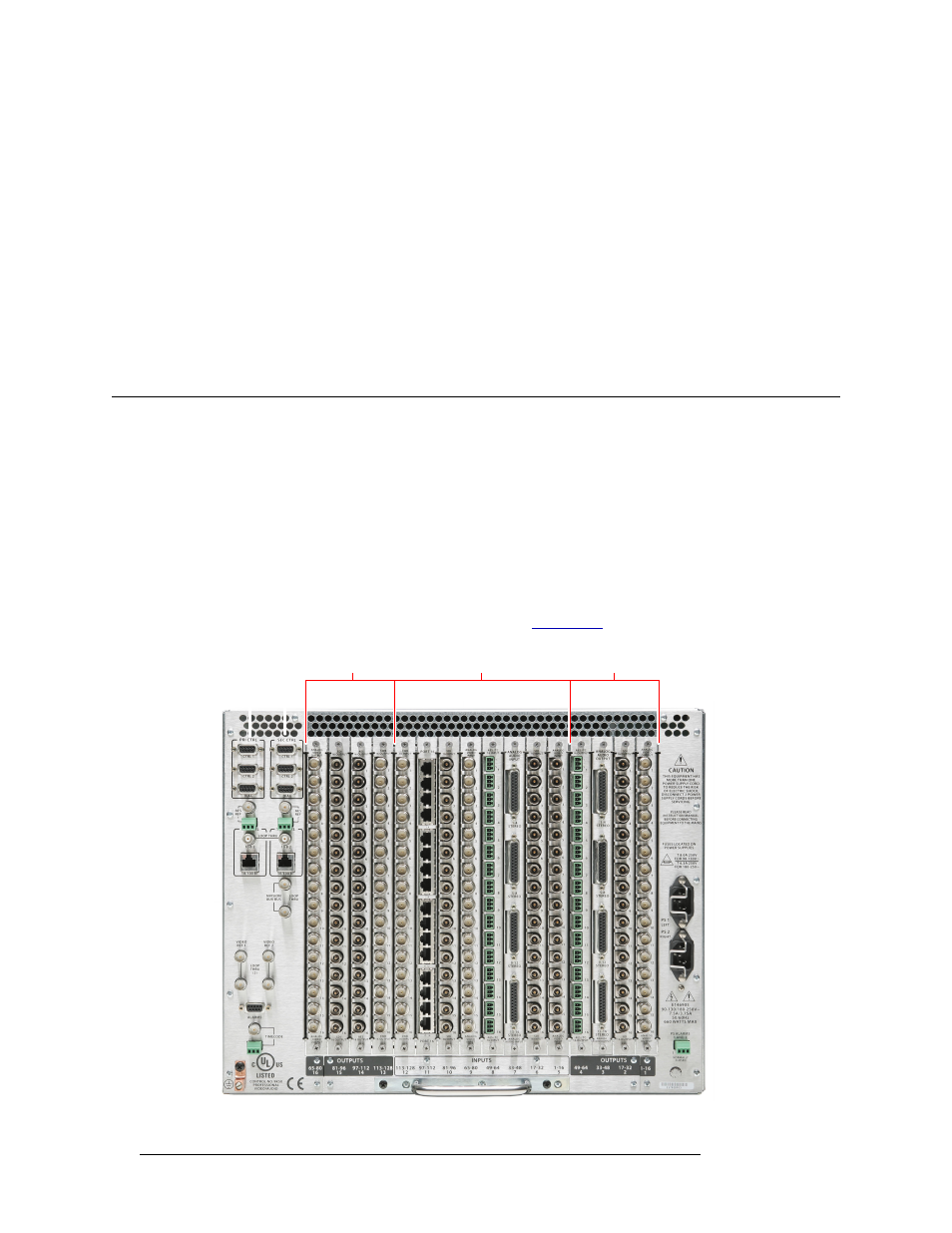
Figure 3-3 shows the backplanes installed on the rear of the router. For more information about
backplanes, and the type of signal supported, see
Figure 3-3. NV5128 Frame with Backplanes (Rear View)
Output 65–128
Input 128–1
Output 64–1
Backplanes