Rear connections, Figure 2-3, next, Figure 2-3.) – Grass Valley NV5128 v.2.5 User Manual
Page 21: Introduction
NV5128 Multi-Format Router • User’s Guide
11
2. Introduction
Module Slots and Rear Connectors
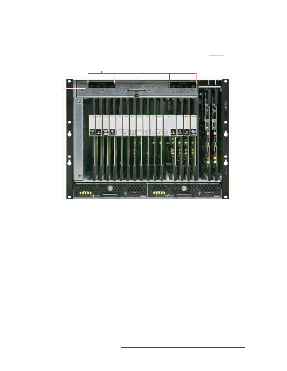
Figure 2-3 shows the location of the input card, output cards, and control card slots, as viewed from
the front.
Figure 2-3. NV5128 Frame with Modules (Front View)
Rear Connections
The rear of the NV5128 (Figure 2-4) features a back plate containing backplanes for receiving and
distributing signals. Backplanes plug into connectors located on the motherboard, which runs the
width of the frame. In the left-hand region are connections for system functions, as shown in
Figure 2-7 on page 16. Two AC power connections are located in the right-hand region.
Slots 1–4
(Outputs 1–64)
Slots 5–12
(Inputs 1–128)
Slots 13–16
(Outputs 128–65)
Primary
Control Card
Secondary
Control Card
Pullout
Fan Tray
Main PS6000 Power Supply
Redundant PS6000 Power Supply