Fuse replacement, Indicator leds, Fuse replacement indicator leds – Grass Valley NV5128 v.2.5 User Manual
Page 86: Fuse replace, Ment, Ion, see, Indica, Tor leds, Refer to, Maintenance
76
Rev 2.5 • 24 Sep 09
6. Maintenance
Fuse Replacement
4 Look at the control card(s) and verify that the green and amber LED's are illuminated on the
active controller, and that the green LED is ON for the standby controller (if present). Verify
that the low battery LED is off on one or both control cards. Refer to
page 76 for a description of the various LEDs and their meaning.
5 Inspect the air intake filter located inside the door. If the filter is dirty or clogged, refer to the
next section for information on how to clean it.
6 Next, move around to the rear of the matrix frame. Ensure that there are no missing backplane
cover plates. Replace any missing cover plates to ensure proper cooling in the frame.
7 Place a hand near the air exhausts. Strong air pressure should be felt evenly across the entire
opening.
8 Check cable connectors for any sign of unseating.
9 Verify that one or both AC cords are firmly seated at both ends. Make sure that the spring bail
power cord retainers on the rear of the frame are in place.
Fuse Replacement
If a problem occurs on a card, the first thing to do is check the fuses.
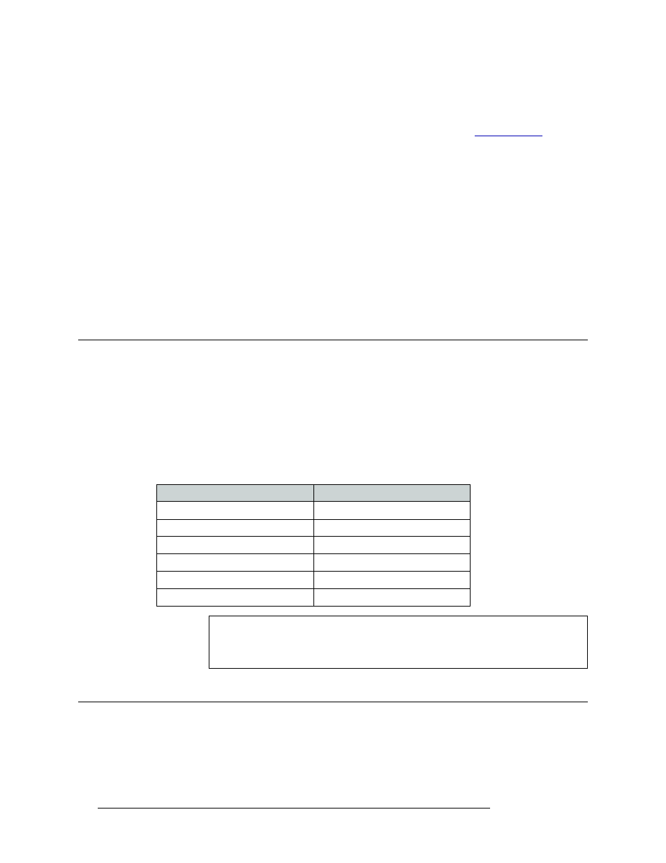
Fuses are located on each of the router’s active cards. Each card features either a “fast blow” or a
fuse that can be reset (“slow blow”). If the card requires a large amount of power, the fuse is “fast
blow” and must be replaced if blown. If the fuse can be reset, reset the fuse by removing the card
from the frame and letting the card temperature cool down. When the fuse temperature reduces to a
safe operating temperature, the fuse automatically resets itself and the card can be reinstalled. The
following table lists the fuses on each card:
Indicator LEDs
Indicator LEDs indicate whether AC power is present and if a card is operating normally. LEDs are
visible when the router front door is closed. In the following sections, LEDs are listed in the order
they appear on the cards, from top to bottom.
Card or Module
Fuse Value
Power supply AC Line Fuse
8 amp, 5
× 20 mm, slow-blow
Control card
1 amp
Crosspoint card
1 amp
Input card
1 amp
Output card
1 amp
Monitor card
1 amp
Warning
Dangerous voltages are present at the rear AC power connector and on the power
supply module. Take precautions to prevent electric shock: Do not touch exposed
wires or connecting pins.