Machine control breakout panel, Machine con, Trol breakout panel – Grass Valley NV5128 v.2.5 User Manual
Page 53: Installation
NV5128 Multi-Format Router • User’s Guide
43
3. Installation
Installing Backplanes
Machine Control backplanes must be installed in specific slots, as follows:
3 Use a #1 Phillips screwdriver to tighten the two spring-loaded backplane retention screws.
4 To maintain proper airflow for cooling, cover any unused backplane slots with a blank plate.
Machine Control Breakout Panel
Miranda offers an optional breakout panel (BP2-PORT-64) that can be used with up to 4 machine
control backplanes. This 4RU breakout panel connects internally 64 RJ-45 connectors to 64 DE9
connectors. For more information, see
Machine Control Breakout Panel
The breakout panel allows you to use DE9 cables to your machine control devices.
How to install a Breakout Panel
1 Rack-mount the (4RU) breakout panel in a convenient location.
2 Cable one or more of its RJ-45 connectors to machine control ports of the NV5128.
3 Cable the matching DE9 connector(s) to the machine control devices (VTRs, etc.) that corre-
spond to the ports.
You can use any of the RJ-45/DE9 connector pairs on the breakout panel that you wish.
Installing Other Video, Audio and Time-Code Backplanes
After installing any Classic SWB or Machine Control backplanes, you can install any other needed
video, audio or time code backplanes. Install input and output backplanes in their respective loca-
tions as defined by your plan for populating the frame. Be careful not to confuse input backplanes
with output backplanes, and make certain that each backplane is installed in the correct slot.
How to install a backplane
1 Unseat any SD input cards and SD output cards before removing or installing SD backplanes.
All other backplanes may be “hot swapped”.
2 Facing the rear of the router, remove any blank plate covering the desired slot by loosening the
spring-loaded module retention screws using a #1 Phillips screwdriver. Gripping the screws,
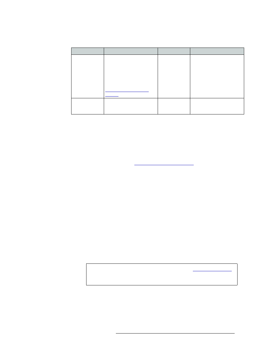
Configuration
Card Set 1
Card Set 2
Backplane Modules
32-port (1–32)
Install this card set in any two
adjacent slots. Slots 11 and 12
are the preferred locations.
Note: you cannot install this
card slot in slots 13 and 14
unless a jumper is moved out of
its “normal” position. See
Machine Control Card Set
Jumpers
—
Install two machine control
backplanes (EM0483) in rear
slots corresponding to the
front-loaded machine control
card set
64-port (1–32,
33–64)
Install in slots 11 and 12
Install in slots 13
and 14
Install four machine control
backplanes (EM0483) in rear
slots 11, 12, 13 and 14
Caution
Be sure to cover any unused slots with blank plates. (See
on page 40.) Leaving openings in the rear may cause the frame to run warmer
than desired, possibly resulting in reduced reliability.